Car carrier binder
A technology of binding device and car carrier, which is applied to goods transport vehicles, vehicles used for freight, motor vehicles, etc., can solve the problems of large space occupation, impact on convenience, and increase in size, etc., and achieves a high degree of automation and improved Convenience, compact effect
- Summary
- Abstract
- Description
- Claims
- Application Information
AI Technical Summary
Problems solved by technology
Method used
Image
Examples
Embodiment 1
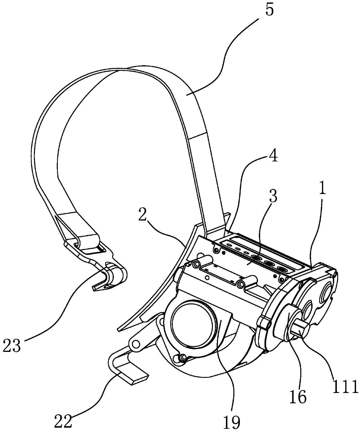
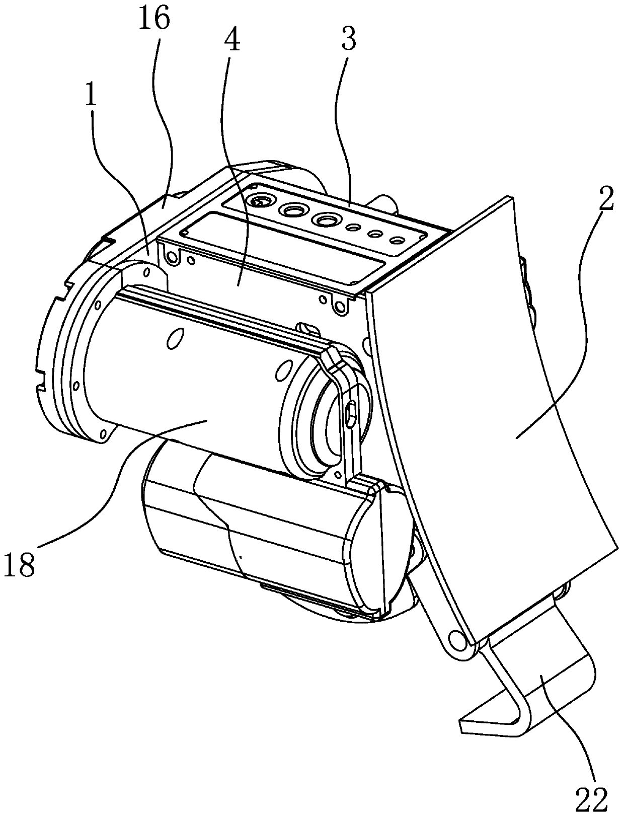
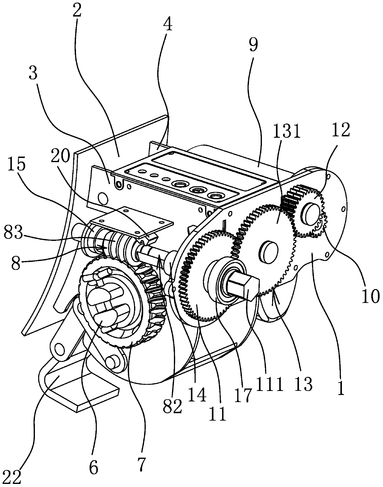
[0043] Such as figure 1 and figure 2 As shown, the binding device for the car transporter includes a binding belt 5, a mounting plate 1, and an abutment plate 2. The installation plate 1 is flat, the abutment plate 2 is arc-shaped, and the concave surface of the abutment plate 2 is facing outward so that It fits snugly with the wheel surface, and in order to increase friction, such as Figure 11 As shown, a rubber pad 25 can also be provided on the outer surface of the abutment plate 2 . The inner side of the abutment plate 2 is fixedly connected with a side plate one 3 and a side plate two 4 oppositely arranged, the side plate one 3 and the side plate two 4 are parallel to each other, and the mounting plate 1 and the side plate one 3 are perpendicular to each other. A hook one 22 for hooking on the truck floor is connected between the side plate one 3 and the side plate two 4 . The outer surface of mounting plate 1 is fixedly provided with gear cover one 16, and the outer...
Embodiment 2
[0054] The structure and principle of this embodiment are basically the same as that of Embodiment 1, except that the transmission structure includes a driving gear 10 connected to the driving member 9, and one end of the worm 8 passes through the mounting plate 1 and is sleeved with a driven gear 11 , The driven gear 11 rotates synchronously with the worm screw 8, and a drive belt is set between the driving gear 10 and the driven gear 11 to make the two rotate synchronously. The driving part 9 drives the driving gear 10 to rotate, and then relies on the belt to drive the driven gear 11 to rotate, and then realizes the rotation of the worm 8 .
Embodiment 3
[0056] The structure and principle of this embodiment are basically the same as that of Embodiment 1, the difference is that the driving member 9 includes a motor and a reducer, the rotating shaft of the motor is connected to the input shaft of the reducer, and the driving gear 10 is connected to the output shaft of the reducer .
PUM
 Abstract
Description
Claims
Application Information
 - R&D
- Intellectual Property
- Life Sciences
- Materials
- Tech Scout
- Unparalleled Data Quality
- Higher Quality Content
- 60% Fewer Hallucinations
Browse by: Latest US Patents, China's latest patents, Technical Efficacy Thesaurus, Application Domain, Technology Topic, Popular Technical Reports.
© 2025 PatSnap. All rights reserved.Legal|Privacy policy|Modern Slavery Act Transparency Statement|Sitemap|About US| Contact US: help@patsnap.com


