
Short-distance branch terminal tightening and automatic locking strained tensioner

A technology of branch lines and tighteners, applied in the direction of overhead lines/cable equipment, etc., can solve the problem that branch wires cannot be completed at one time

Inactive Publication Date: 2017-10-27
郑善彬
View PDF0 Cites 0 Cited by
  • Summary
  • Abstract
  • Description
  • Claims
  • Application Information

AI Technical Summary

Problems solved by technology

2. Due to the limitation of environmental and geographical conditions, when the branch wires to be T-connected are tightened, it cannot be completed at one time.

Method used


Image

  • Short-distance branch terminal tightening and automatic locking strained tensioner
  • Short-distance branch terminal tightening and automatic locking strained tensioner
  • Short-distance branch terminal tightening and automatic locking strained tensioner

Examples


Embodiment Construction

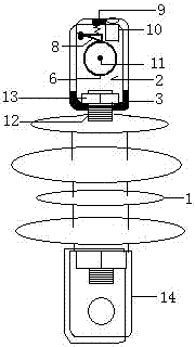
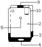
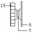
[0010] attached figure 1 shows the structure of the present invention, the figure 1 The top of terminal tension insulator 1 is provided with terminal locking tensioner 2, the bottom of terminal locking tensioner 2 is provided with first reinforced tension plate 3, and the bottom of first reinforced tensioner 3 is set at the middle position figure 2 Threading hole 4, pin hole 5 is set in the middle of the front, and pin hole 5 is set inside image 3 Tension ratchet 6, anti-slip ribs 7 are set on the winding shaft surface in the middle of the tension ratchet 6, and the top of the tension ratchet 6 is set figure 1 Ratchet pawl 8, figure 1 A second reinforced tension plate 9 is arranged at the middle position on the top of the terminal lock tightening device 2, and a three-jaw clamp 10 with inverted tooth pattern inside is arranged at one end of the second reinforced tension plate 9.

[0011] The assembling process of the present invention is: at first will image 3 Tension r...


PUM


Abstract

The invention discloses a short-distance branch line terminal tightening automatic stop tension tensioner, because a tension ratchet is arranged in the terminal locking tension tensioner, and a ratchet stop pawl is arranged at the top of the tension ratchet. Yes: When the wire to be tightened bypasses the tension ratchet to tighten and stop, the ratchet stop pawl can be set on the top of the tension ratchet to stop the tension ratchet (the wire can have resistance in the ratchet groove and cannot be forcibly slowed to the receiving ratchet. pull end). After the tension ratchet is stopped by the ratchet stop pawl, the tension ratchet can also be used as a wire reversing pile. In addition, due to the adoption of a three-jaw clamp with inverted teeth inside at one side of the second reinforced tension plate, its characteristic is that when the wire to be tightened is completely tightened, the inside has inverted teeth The special three-jaw clamp can realize that the tightened wire can be finally clamped again (the wire can not be forcibly retreated to the tensioned end in the tension ratchet).

Description

[0001] technical field [0002] The invention relates to the erection of power transmission lines, and directly relates to a tension-resistant tensioner with automatic stop for tightening the terminals of short-distance branch lines, and is especially suitable for the construction of short-distance overhead wires in special occasions. Background technique [0003] After the construction of the main wire frame of the electric power is completed, a T-connection branch line should be implemented on the main wire to the branch equipment. The construction method of the T-connection branch line is the same as that of the main wire frame installation method. During the construction, it was found that the branch wires that were T-connected to the branch equipment were not standardized. The reasons were as follows: 1. Due to the short distance between the branch equipment and the main wire, it was not possible to use large tightening tools to complete it. 2. Due to the limitation of en...

Claims


Application Information

Patent Timeline
IPC IPC(8): H02G1/04
CPCH02G1/04
Inventor 郑善彬王芹
Owner 郑善彬
Learn More