Large-span steel structure staggered-layer closure installation method

An installation method and technology of steel structure, applied in the direction of building structure, construction, building material processing, etc., can solve the problem of work can not be carried out, and achieve the effect of increasing stability, reducing bending moment and reducing quantity

Active Publication Date: 2019-05-10
BEIJING NO 3 CONSTR ENG
View PDF6 Cites 4 Cited by
  • Summary
  • Abstract
  • Description
  • Claims
  • Application Information

AI Technical Summary

Problems solved by technology

In this method, since the support frame 3 bears all the weight of the steel beam 2, multiple support frames 3 need to be provided, and the support frame foundation is strong enough to support the entire structure. When the structure is closed, the closing temperature required by the design must be reached. Subsequent work cannot be performed before collapse

Method used


Image

  • Large-span steel structure staggered-layer closure installation method
  • Large-span steel structure staggered-layer closure installation method
  • Large-span steel structure staggered-layer closure installation method

Examples


Embodiment

[0044] The invention discloses a large-span steel structure staggered closing installation method, which includes the following construction steps:

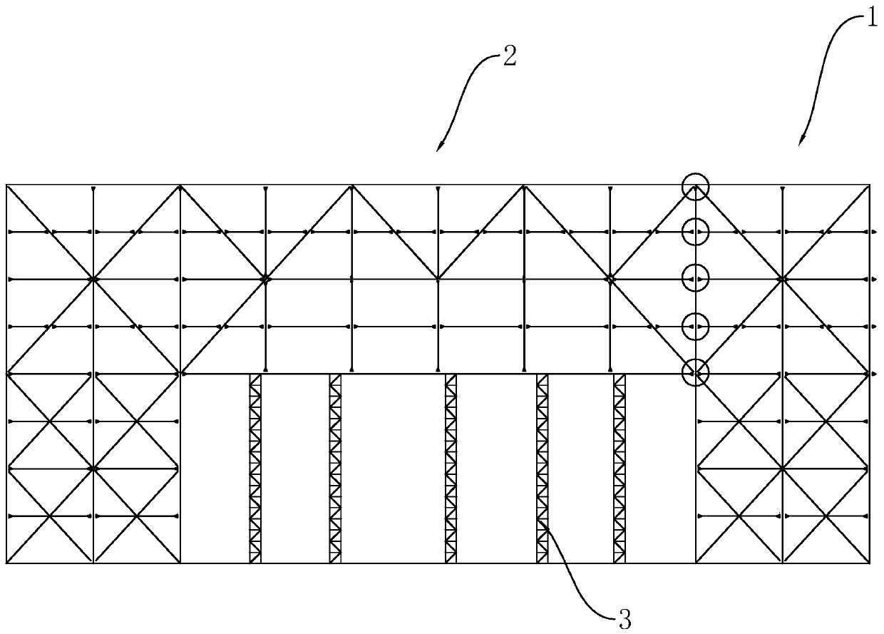
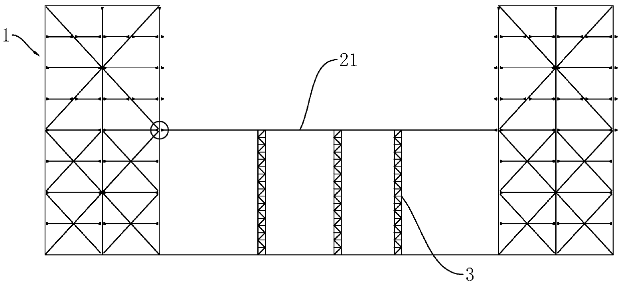
[0045] S1. Support frame installation: refer to figure 2 Firstly, the ground below the steel beam 2 is rolled and concrete is poured to harden, so as to enhance the compressive capacity of the ground, prevent the subsidence of the ground foundation, and improve the safety in the construction process and the accuracy of the installation of the steel beam 2 . Three rows of support frames 3 are installed on the ground for supporting the steel beams 2 .

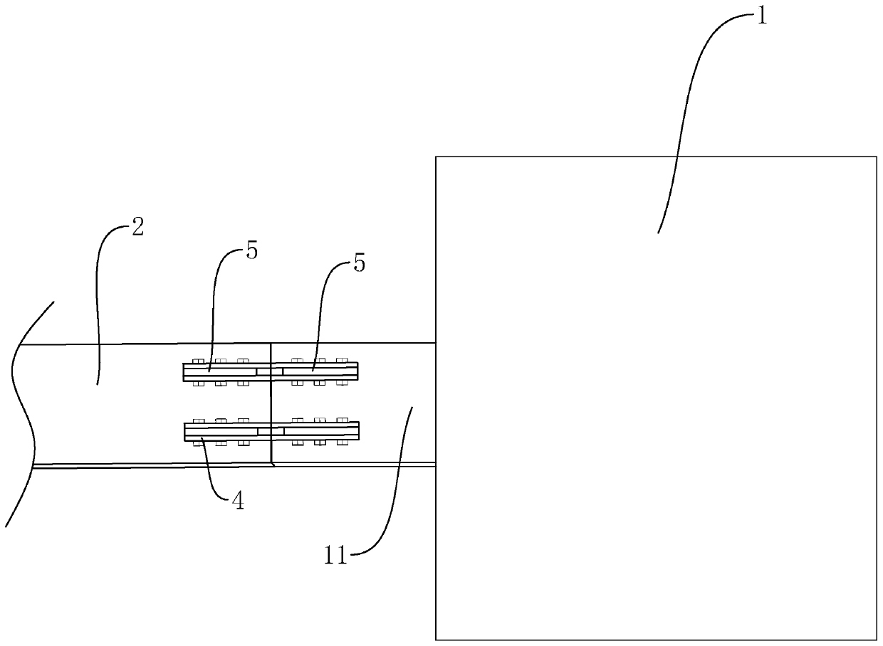
[0046] S2. Installation of beams on the first floor: refer to figure 2, hoist the first floor beam 21 to the installation position and make the support frame 3 support the first floor beam 21, butt one end of the first floor beam 21 with the corbel 11 on one side of the core tube 1 and then weld and fix it, and the other end and the other The corbel 11 on one side core tube 1 is...


PUM


Abstract

The invention relates to a large-span steel structure staggered-layer closure installation method. The method comprises the following construction steps that S1, installing a supporting frame; S2, mounting a first-layer beam: namely fixing one end of the first-layer beam to a bracket on a core tube on one side, disconnecting and temporarily connecting the other end of the first-layer beam with a bracket on the core tube on the other side; S3, installing a first-section supporting column and a second-layer beam: specifically, fixedly arranging the first-section supporting column on the first-layer beam, installing the second-layer beam in a segmented mode, and making the disconnection position opposite to that of the first-layer beam; S4, mounting a third-layer beam: hoisting the three-layer beam to a mounting position in a segmented manner, fixedly connecting the bottom of the third-layer beam with the top end of the first-section supporting column, and making the disconnecting position of the third-layer beam the same as that of the first-layer beam; S5, installing a tail-section supporting column, a backwards counted second-layer beam and a top-layer beam, specifically, making the disconnecting positions of the backwards counted second-layer beam and the top-layer beam with the core tube opposite to the disconnecting positions of one adjacent lower-layer beam and the backwards counted second-layer beam, respectively; and S6, welding the disconnected position of a steel beam and the core tube. The construction method has the advantages of high construction efficiency and cost saving.

Description

technical field [0001] The invention relates to the technical field of steel structure construction, in particular to a staggered-level installation method for a long-span steel structure corridor. Background technique [0002] Currently, refer to figure 1 , in the installation of large-span steel structures, the installation method of conventional steel structures is that the structure is installed layer by layer and finally closed, that is, one end of the steel beam 2 is fixed to the corbel on the core tube 1 on one side of the steel beam 2, The other end is disconnected from the core tube 1 on the other side of the steel beam 2, and the disconnected position of each layer of steel beam 2 and core tube 1 is located on the same side, and the lower end of the steel beam 2 is provided with a support frame 3 to support the steel beam 2. In this method, since the support frame 3 bears all the weight of the steel beam 2, multiple support frames 3 need to be provided, and the su...

Claims


Application Information

Patent Timeline
Patent Type & Authority Applications(China)
IPC IPC(8): E04B1/342E04G21/18
Inventor 罗刚张钢孙凯刘垚崔少鹏陈雪吴晨希郭鹏飞
Owner BEIJING NO 3 CONSTR ENG
Why Eureka
Try Eureka