Variable-rigidity vertical vibration isolation/ seismic isolation support

A variable stiffness and vertical technology, applied in the fields of walls, disaster prevention and reduction, and construction, can solve problems such as complex settings

Active Publication Date: 2019-05-10
永富建工集团有限公司
View PDF7 Cites 5 Cited by
  • Summary
  • Abstract
  • Description
  • Claims
  • Application Information

AI Technical Summary

Problems solved by technology

However, the above lite

Method used


Image

  • Variable-rigidity vertical vibration isolation/ seismic isolation support
  • Variable-rigidity vertical vibration isolation/ seismic isolation support
  • Variable-rigidity vertical vibration isolation/ seismic isolation support

Examples


Embodiment 1

[0034] Embodiment 1: CN100478539A provides the technical idea of ​​variable stiffness vibration isolation, which relies on pre-compressed springs and compensation springs to achieve. However, it has the following problems:

[0035] (1) When the compensation support is lowered, the compensation spring can participate in the work under pressure; however, the compensation spring is separated from the compensation support under normal conditions; when the compensation support moves up, how can the compensation spring participate in the work? Pull, not elaborated in the literature;

[0036] (2) Whether the preload spring can be preloaded in other ways.

[0037] The starting point of the invention of this application is to solve the second problem. The preloading in CN100478539A is initially realized by the weight of the building. Then, this method is not conducive to the installation of the support; preload.

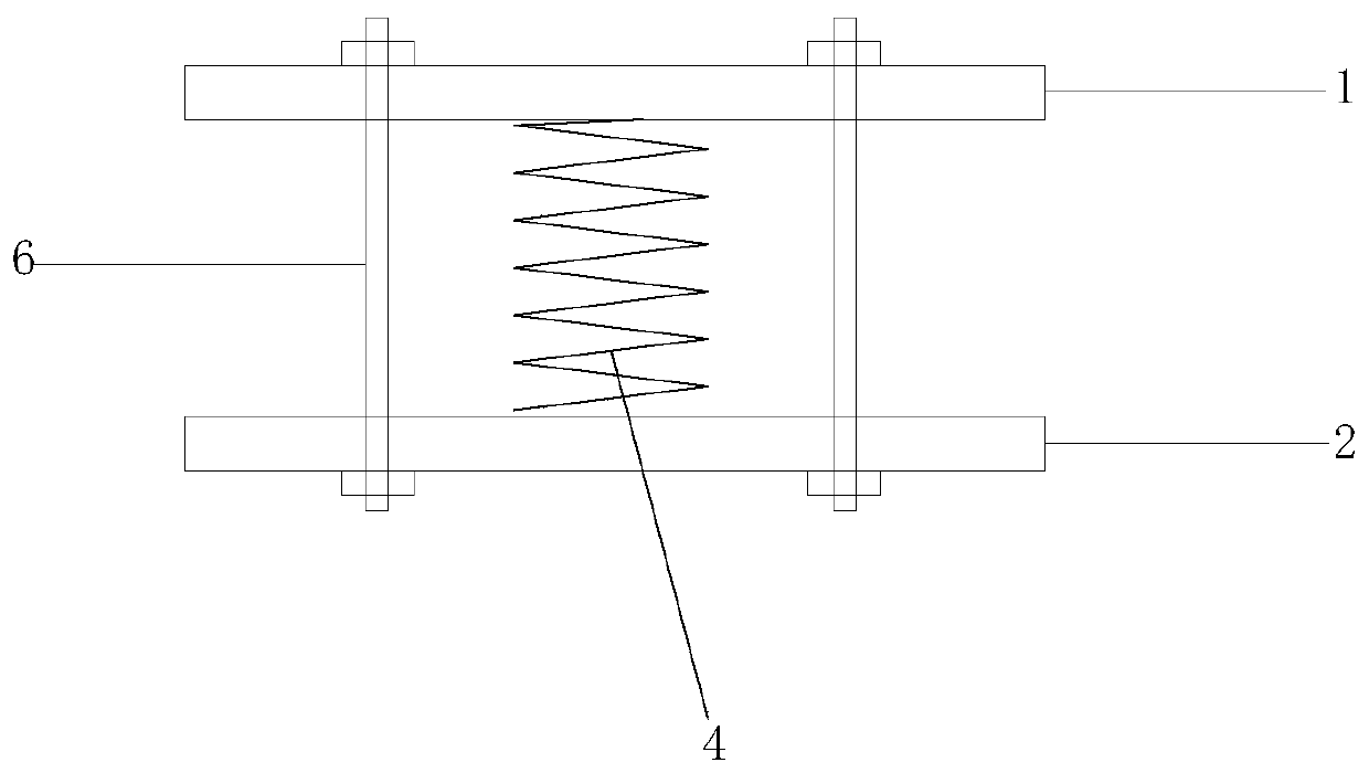
[0038] Such as figure 1 As shown, a preload spring 4 is installed be...

Embodiment 2

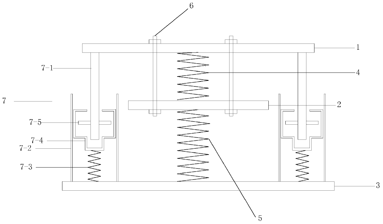
[0059] Embodiment 2, in order to make the spring participate in tension, a more reasonable design should be: in the initial state (static load), the upper surface of the protrusion 7-5 and the adjustment cavity 7-4; the difficulty lies in how to install the pressure Rod 7-1;

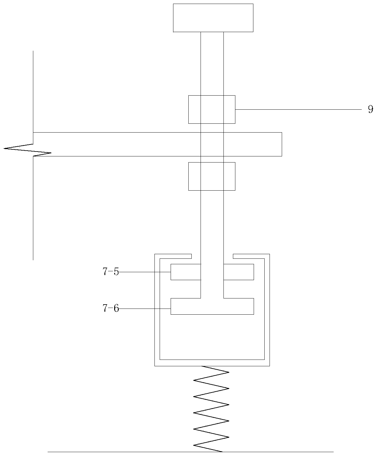
[0060] The pressure rod 7-1 is installed in the initial state, the pressure rod 7-1 passes through the first horizontal plate 1, the outer surface of the pressure rod 7-1 is provided with threads, and the upper part of the pressure rod 7-1 is provided with 2 threads Cap 9, two threaded caps 9 are respectively located on the top and bottom of the first horizontal plate 1, after the height of the pressure rod 7-1 is adjusted, then the two threaded caps 9 are used to clamp the pressure rod 7-1 on the first level. Horizontal plate 1, and then fix pressure bar 7-1.

[0061] Embodiment 2: In the initial state, when the distance between the bottom of the pressure rod and the adjustment cavity 7-4 is greater th...

Embodiment 3

[0065] Embodiment 3: A viscous damper 11 is installed between the first horizontal plate and the third horizontal plate, and the viscous damper is arranged on the outside of the outer wall of the sleeve 7-2.


PUM


Abstract

The invention discloses a variable-rigidity vertical vibration isolation/seismic isolation support. The key points of design are that a pre-pressing spring is installed between a first horizontal plate and a second horizontal plate, a pre-stress tendon is further installed between the first horizontal plate and the second horizontal plate, and two anchors of the pre-stress tendon are anchored to the upper side of the first horizontal plate and the lower side of the second horizontal plate respectively; the pre-pressing spring is in a pre-pressing state by tensioning and anchoring the pre-stressed tendon; a third horizontal plate is arranged below the second horizontal plate, and a second spring is connected between the second horizontal plate and the third horizontal plate; a spring rigidity adjusting device is mounted between the first horizontal plate and the third horizontal plate; the spring rigidity adjusting device comprises a protruding part arranged on the side portion of a pressing rod, and the protruding part of the pressing rod is arranged in an adjusting cavity; under the action of a static vertical load G, the second spring provides supporting rigidity, the design requires that G is less than the pre-pulling force F of the pre-stressed tendon and is the initial state, and the second spring is in the initial state, the distance between the bottom of the pressing rodand the adjusting cavity is greater than or equal to (F-G)/K2.

Description

technical field [0001] The invention relates to the fields of buildings, walls, disaster prevention and reduction, etc., and in particular to a vertical vibration isolation / seismic support with variable stiffness. Background technique [0002] Professor Yan Weiming of Beijing University of Technology invented the text in China: CN100478539A, which proposed a vertical vibration isolation / seismic support with variable stiffness and variable damping, which belongs to the field of structural vibration control. It includes upper and lower connecting plates, a pre-compression spring with a small vertical stiffness, a variable stiffness compensation spring with a large vertical stiffness, a small oil damper set in the pre-compression spring, and a large oil damper set in the compensation spring. oil damper. The variable stiffness compensation spring is located at the center of the lower connecting plate, and its upper end penetrates into the first reserved hole of the first compen...

Claims


Application Information

Patent Timeline
IPC IPC(8): E04B1/36E04B1/98E04H9/02
Inventor 田丽
Owner 永富建工集团有限公司
Why Eureka
Try Eureka