Special thin plate clamping device for manufacturing metal material indentations
A metal material and clamp technology, applied in the direction of analyzing materials, manufacturing tools, instruments, etc., can solve the problems of affecting the reliability of experimental measurement accuracy and data, and the instability of non-flat sheet workpiece samples, achieving simple structure and strong adaptability. , easy to use effect
- Summary
- Abstract
- Description
- Claims
- Application Information
AI Technical Summary
Problems solved by technology
Method used
Image

Examples
Embodiment 1
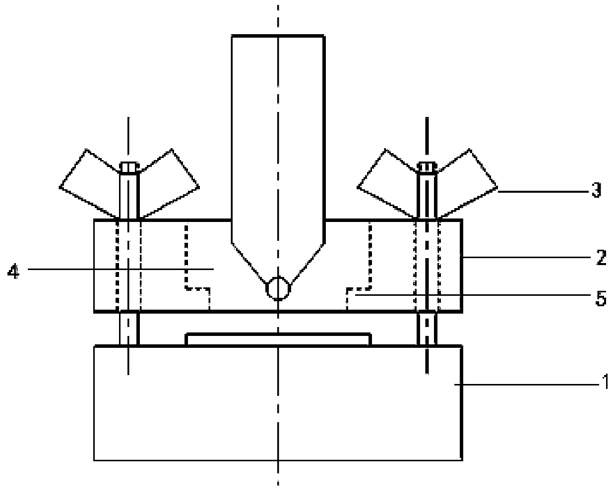
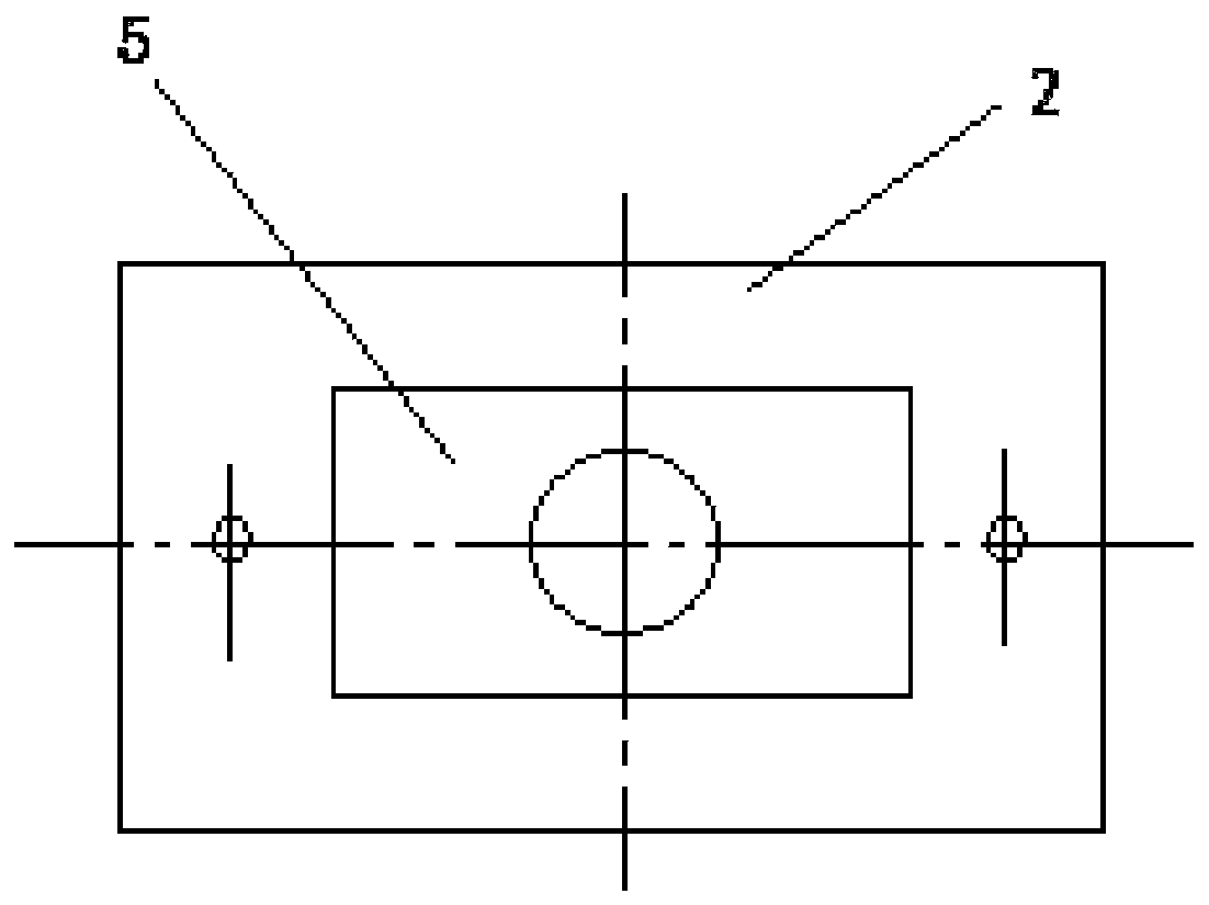
[0019] In this example, see figure 1 and figure 2 , a metal material indentation manufacturing special thin plate clamp, including a base 1, an upper plate 2 and a wing nut 3, the upper plate 2 is provided with a groove 4, in the middle of the bottom of the groove 4 is provided with a circular The hollow structure makes the rest of the bottom of the groove located on the periphery of the circular hollow structure form a concave platform 5, and on the outside of the groove 4, round holes are symmetrically distributed around the groove 4, and the studs are fixed on the base 1, and the studs are connected from the top. Through the round hole around the groove 4 of the pressure plate 2, the wing nut 3 and the threaded part of the stud can be fastened and fastened. Two wing nuts 3 are set to form two connection point structures with the corresponding studs respectively. , so that the two wing nuts 3 are respectively located on both sides of the groove 4, a thin plate workpiece ca...
Embodiment 2
[0023] This embodiment is basically the same as Embodiment 1, especially in that:
[0024] In this embodiment, 4 wing nuts 3 are set to form 4 connection point structures with corresponding studs respectively, so that the two wing nuts 3 are respectively located on the left and right sides of the groove 4, and are connected at 4 points to enhance the connection. The stability of the clamping and fixing of thin plate workpieces. In this embodiment, the special thin plate clamp for indentation manufacturing of metal materials places the thin plate sample on the base 1, uses the concave platform 5 on the upper platen 2 to flatten and press the thin plate, and turns the butterfly nut 3 to fix the sample, so that the equipment The indenter conducts experiments on thin plate specimens through the circular hollow hole in the center of the upper platen to achieve the purpose of flattening and fixing the tested surface of the sample. , the experiment can be carried out smoothly, and t...
Embodiment 3
[0026] This embodiment is basically the same as the previous embodiment, and the special features are:
[0027] In this embodiment, four wing nuts 3 are set to form four connection point structures with the corresponding studs, so that the two wing nuts 3 are respectively located on the left and right sides and the front and rear sides of the groove 4, and through four points Connection to enhance the stability of clamping and fixing thin plate workpieces. In this embodiment, the special thin plate clamp for indentation manufacturing of metal materials places the thin plate sample on the base 1, uses the concave platform 5 on the upper platen 2 to flatten and press the thin plate, and turns the butterfly nut 3 to fix the sample, so that the equipment The indenter conducts experiments on thin plate specimens through the circular hollow hole in the center of the upper platen to achieve the purpose of flattening and fixing the tested surface of the sample. , the experiment can b...
PUM
| Property | Measurement | Unit |
|---|---|---|
| height | aaaaa | aaaaa |
| length | aaaaa | aaaaa |
| width | aaaaa | aaaaa |
Abstract
Description
Claims
Application Information
 - R&D
- Intellectual Property
- Life Sciences
- Materials
- Tech Scout
- Unparalleled Data Quality
- Higher Quality Content
- 60% Fewer Hallucinations
Browse by: Latest US Patents, China's latest patents, Technical Efficacy Thesaurus, Application Domain, Technology Topic, Popular Technical Reports.
© 2025 PatSnap. All rights reserved.Legal|Privacy policy|Modern Slavery Act Transparency Statement|Sitemap|About US| Contact US: help@patsnap.com