
Gridded high-speed railway supporting layer concrete wave velocity detection device and estimation method

A technology for high-speed railways and detection devices, which is applied in the direction of using sound waves/ultrasonic waves/infrasonic waves to analyze solids, etc. It can solve the problem of not meeting the needs of large-area detection of concrete strength in the support layer, the inability to refine the detection of different distributions of concrete strength, and the inability to obtain concrete strength. and other problems, to achieve the effect of improving the maintenance level, refining the detection scale, and simple operation

Pending Publication Date: 2019-05-10
SHIJIAZHUANG TIEDAO UNIV
View PDF0 Cites 6 Cited by
  • Summary
  • Abstract
  • Description
  • Claims
  • Application Information

AI Technical Summary

Problems solved by technology

The drilling core sampling method has the following disadvantages: (1) The sampling location is the edge of the support layer, and the concrete strength at the center of the lower part of the track slab cannot be obtained; (2) The drilling core sampling destroys the integrity of the structure and aggravates the deterioration rate of the structure; ( 3) Drilling core sampling is random, which cannot meet the needs of large-area testing of the concrete strength of the support layer
At present, the estimation method adopts the single-shot-single-receive (SISO) mode, which is only suitable for the coarse-scale detection of concrete strength, and cannot perform fine-scale detection of different distributions of concrete strength.

Method used


Image

  • Gridded high-speed railway supporting layer concrete wave velocity detection device and estimation method
  • Gridded high-speed railway supporting layer concrete wave velocity detection device and estimation method
  • Gridded high-speed railway supporting layer concrete wave velocity detection device and estimation method

Examples


Embodiment Construction

[0040] The technical solutions in the embodiments of the present invention will be clearly and completely described below in conjunction with the drawings in the embodiments of the invention, but it should be understood that the protection scope of the present invention is not limited by the specific embodiments.

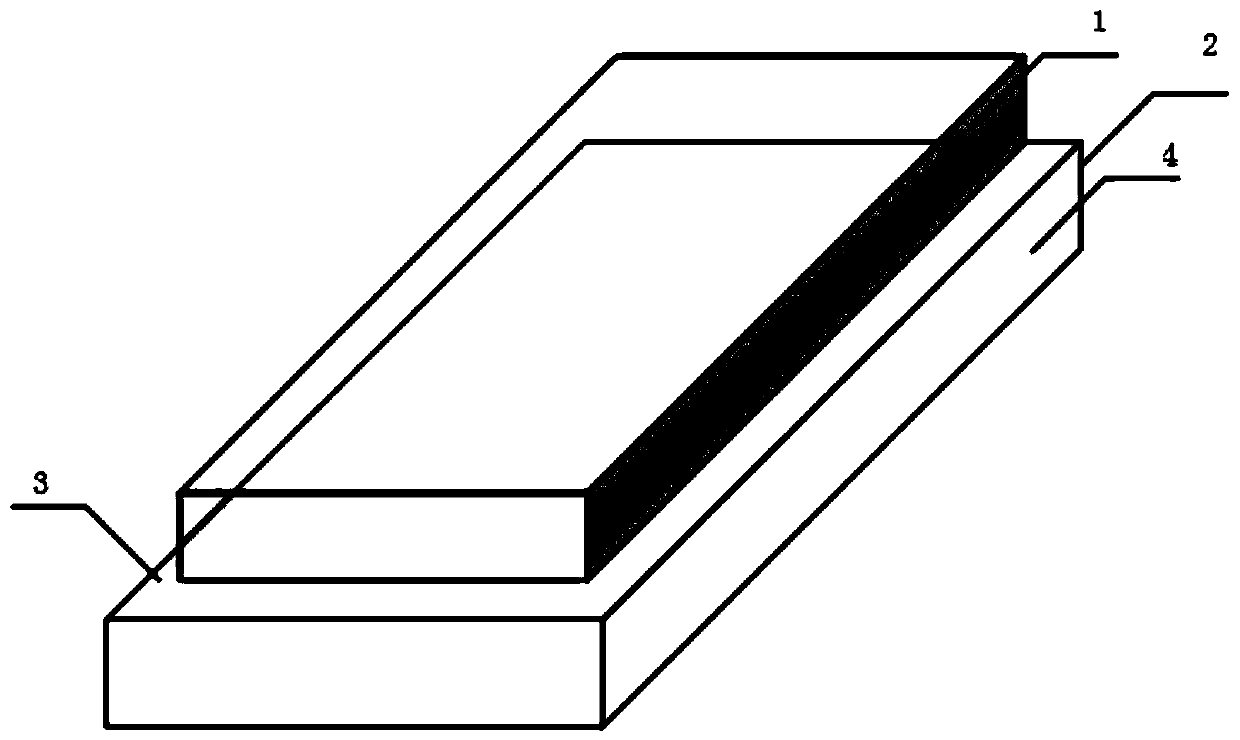
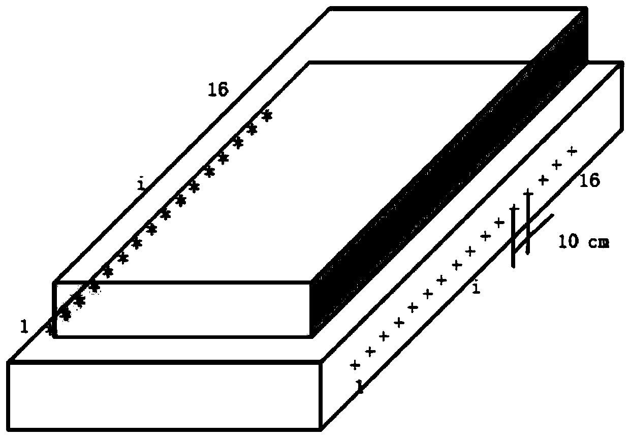
[0041] refer to Figure 1-6 , the present invention provides a gridded high-speed railway support layer concrete wave velocity detection device and estimation method, comprising a track slab 1 and a support layer 2, the track slab 1 is arranged at a middle position above the support layer 2, and the support layer 2. The upper surface is the elastic wave receiving surface 3, and the side surface of the support layer 2 along the extending direction of the track is the elastic wave excitation surface 4;

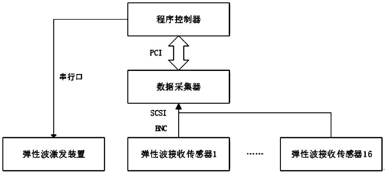
[0042] A plurality of elastic wave excitation devices are arranged horizontally at fixed intervals on the elastic wave excitation surface 4, and a plurality of elasti...


PUM


Abstract

The invention discloses a gridded high-speed railway supporting layer concrete wave velocity detection device and estimation method, and relates to the technical field of nondestructive detection of concrete quality of ballastless tracks of high-speed railway. Firstly, the supporting layer elastic wave velocity detection device is provided; an elastic wave velocity estimation model is built by thegridded estimation method; and based on a loss function under a fine-scale condition and a neural network model of an optimization objective, fine nondestructive detection of the wave velocity in theballastless tracks of the high-speed railway is realized. The problem of fine-scale detection of the concrete strength of the supporting layers of the ballastless tracks of the high-speed railway issolved; the destruction of traditional drill core sampling to the structure is overcome; the detection scale is refined; the detection precision of concrete wave velocity estimation is improved; and the detection device has the characteristics of simple operation, non-destructiveness and high detection precision, is suitable for detection of the concrete wave velocity of the supporting layers, meets the requirement for large-area detection of the internal strength of the supporting layers, and is favorable for improving the maintenance level of the ballastless tracks of the high-speed railwayin China.

Description

technical field [0001] The invention relates to the technical field of non-destructive detection of concrete quality of ballastless track of high-speed railway, in particular to a gridded concrete wave velocity detection device and estimation method of high-speed railway support layer. Background technique [0002] As the carrier of high-speed railway, the ballastless track of high-speed railway has a direct bearing on the operation safety of high-speed railway, whether its quality is good or not, and whether there are internal diseases or not. However, due to the long-term action of external loads such as trains and rainwater environments, the strength of concrete will inevitably decrease. Especially for the cast-in-place supporting layer structure, affected by factors such as the temperature during pouring, the concrete strength cannot meet the design requirements, coupled with long-term rain erosion, the concrete mortar will flow out, the porosity will increase, and the c...

Claims


Application Information

Patent Timeline
IPC IPC(8): G01N29/07G01N29/04
Inventor 杨勇李义强赵维刚田秀淑戎立帆
Owner SHIJIAZHUANG TIEDAO UNIV
Learn More