
A multi-distance detection device and method for a depth camera

A technology of depth camera and distance detection, which is applied to measurement devices, re-radiation of electromagnetic waves, radio wave measurement systems, etc.

Active Publication Date: 2019-05-10
SHENZHEN ORBBEC CO LTD
View PDF5 Cites 1 Cited by
  • Summary
  • Abstract
  • Description
  • Claims
  • Application Information

AI Technical Summary

Problems solved by technology

[0004] The purpose of the present invention is to solve the problem that the detection device of the depth camera is too large when the detection distance increases in the prior art, and propose a multi-distance detection device and method for the depth camera

Method used


Image

  • A multi-distance detection device and method for a depth camera
  • A multi-distance detection device and method for a depth camera
  • A multi-distance detection device and method for a depth camera

Examples


Embodiment Construction

[0018] The present invention will be described in detail below through specific embodiments in conjunction with the accompanying drawings, so as to better understand the present invention, but the following embodiments do not limit the scope of the present invention. In addition, it should be noted that the diagrams provided in the following embodiments are only schematically illustrating the basic concept of the present invention, and only the components related to the present invention are shown in the drawings rather than the number of components, Shape and size drawing, the shape, quantity and proportion of each component can be changed arbitrarily during actual implementation, and the layout of the components may also be more complicated.

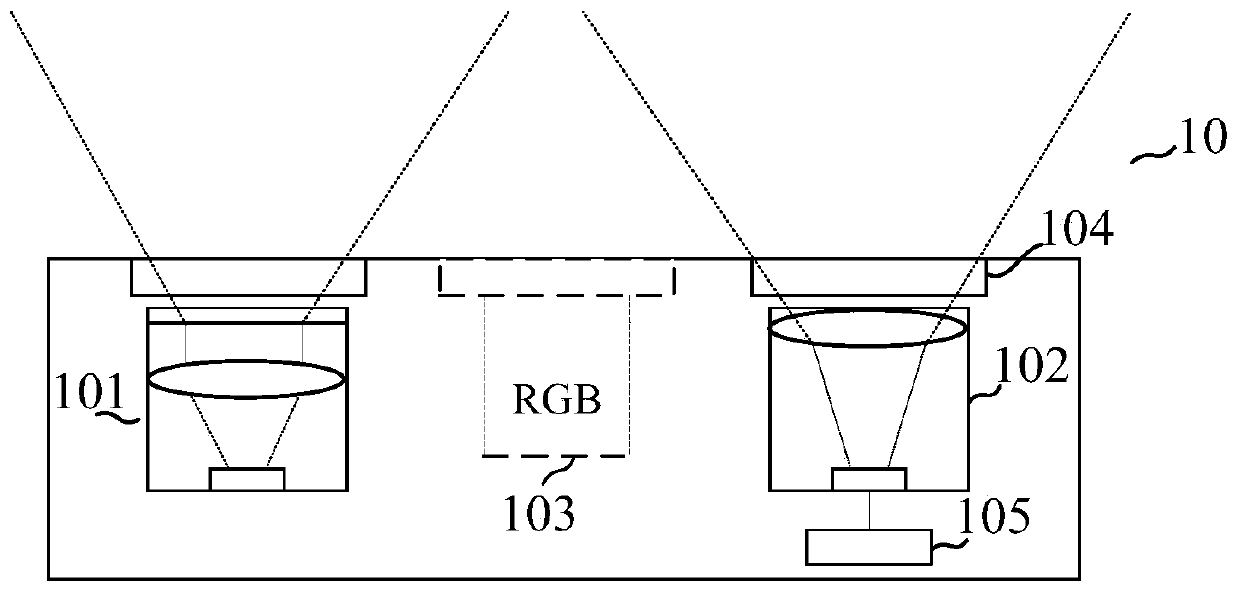
[0019] figure 1 It is a structural diagram of a depth camera. The depth camera 10 includes a plurality of optical modules, such as a projection module 101, an imaging module 102, an RGB camera 103, a light entrance window 104, and a pr...


PUM


Abstract

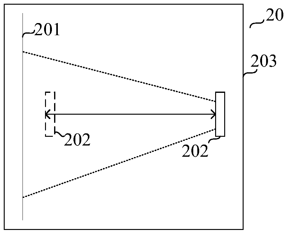
The invention provides a multi-distance detection device for a depth camera, and the device comprises the depth camera which is used for projecting a light beam and receiving the light beam reflectedby a screen; a plane mirror used for reflecting the light beam projected by the depth camera and increasing the projection optical path of the light beam; wherein the screen is a crop plane and is used for receiving the light beam projected by the depth camera or receiving the light beam reflected by the plane mirror and reflecting the light beam, so that the depth camera completes detection; anda shell used for placing the depth camera, the plane mirror and the screen. The invention also provides a multi-distance detection method of the depth camera. According to the multi-distance detectiondevice and method for the depth camera, through the reflection principle of the plane mirror, the plane mirror is placed in the detection device, the light beam projection optical path is increased,and the detection distance can be increased without changing the space size of the device.

Description

technical field [0001] The invention relates to the field of depth cameras, in particular to a multi-distance detection device and method for depth cameras. Background technique [0002] At present, the depth calibration and depth detection of the structured light depth camera are carried out in the same device. The principle is to project the speckle pattern on the white screen through the structured light projection module inside the depth camera, and then perform the depth calibration and depth detection. Due to space constraints, the current calibration distance and depth detection distance are limited within 1.5m. [0003] However, as the application distance of the structured light depth camera increases, such as the rear camera of a mobile phone, there is a greater demand for the depth calibration and depth detection distance of the depth camera. However, according to the existing detection scheme, when the detection (described in this case "Detection" includes "dept...

Claims


Application Information

Patent Timeline
Patent Type & Authority Applications(China)
IPC IPC(8): G06T7/55G06T7/80G01S17/08
Inventor 张太永黄杰凡
Owner SHENZHEN ORBBEC CO LTD
Learn More