

Storage battery grid casting die
A battery and mold technology, applied in the field of casting molds, can solve problems such as grid collision damage, casting liquid waste, grid failure, etc., and achieve the effects of increased yield, thin interlayer, and small weight deviation
- Summary
- Abstract
- Description
- Claims
- Application Information
AI Technical Summary
Problems solved by technology
Method used
Image

Examples
Embodiment Construction
[0009] The present invention will be further described below in conjunction with accompanying drawing.
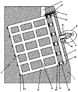
[0010] see figure 1 , the battery grid casting mold of the present invention includes a mold body, a mold cavity is arranged in the mold body, a sprue communicating with the mold cavity is arranged on the mold body, and a material breaking device is arranged in the mold body near the sprue , one side of the mold body is provided with an exhaust passage, and the mold cavity communicates with the exhaust passage through the exhaust port. The exhaust passage is provided with an air outlet, and a negative pressure generator is arranged in the air outlet. The cavity is provided with a temperature detector, the material cutting device is provided with a slider, the mold body is provided with a slide rail, and the material cutting device is slidably connected with the mold body through the slider and the slide rail.
[0011] The invention is simple in structure, easy to operate, ...
PUM
 Abstract
Description
Claims
Application Information