Concrete piston dismounting and mounting tool
A technique for concrete pistons and tools, which is applied in the field of disassembly and assembly tools for concrete pistons, and achieves the effects of convenient mass production, quick assembly and simple structure
- Summary
- Abstract
- Description
- Claims
- Application Information
AI Technical Summary
Problems solved by technology
Method used
Image
Examples
Embodiment 1
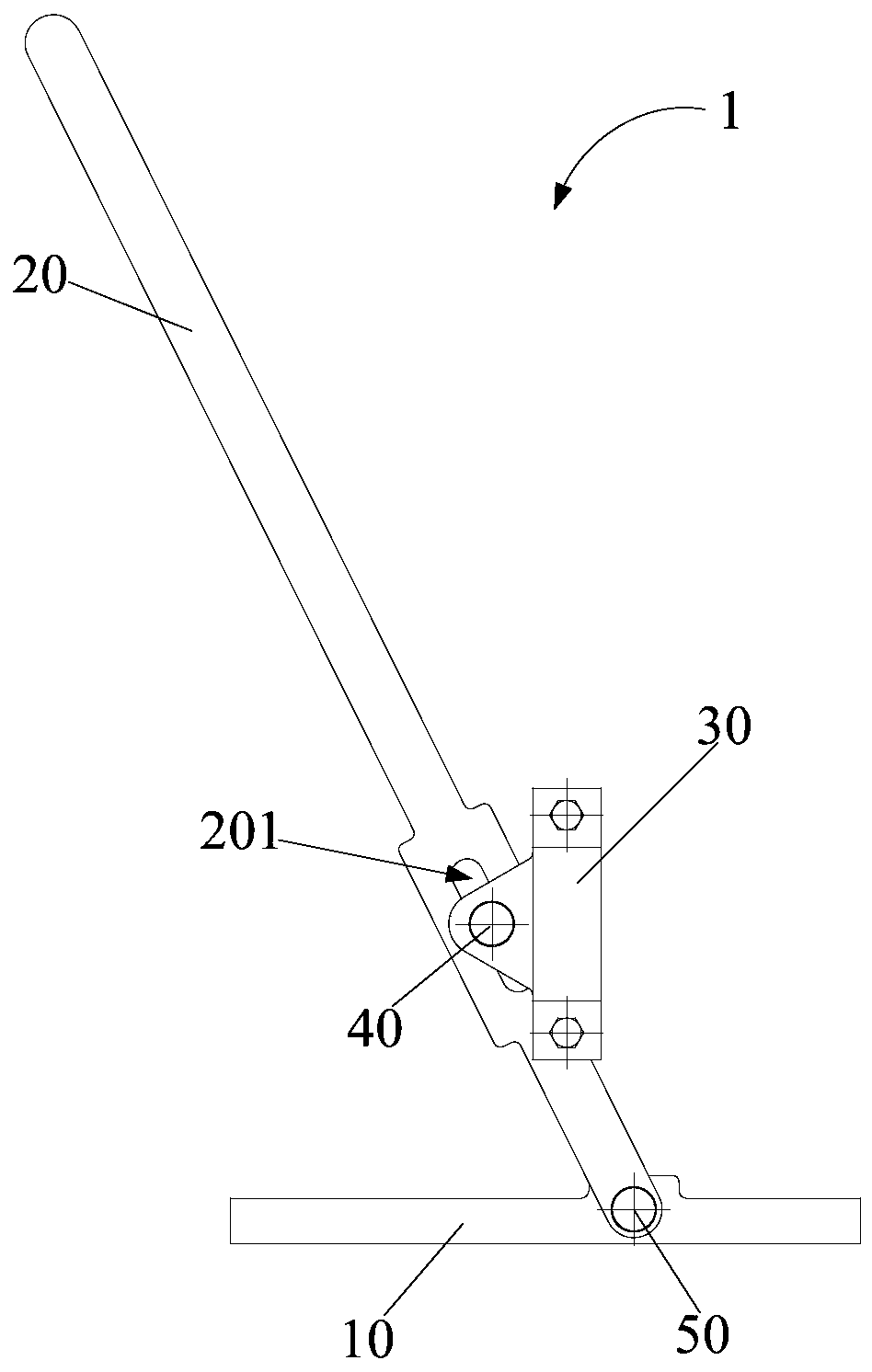
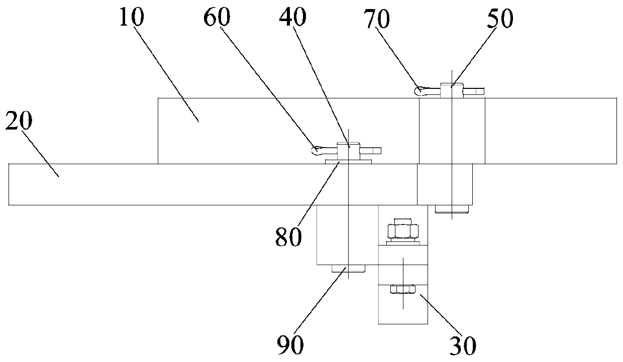
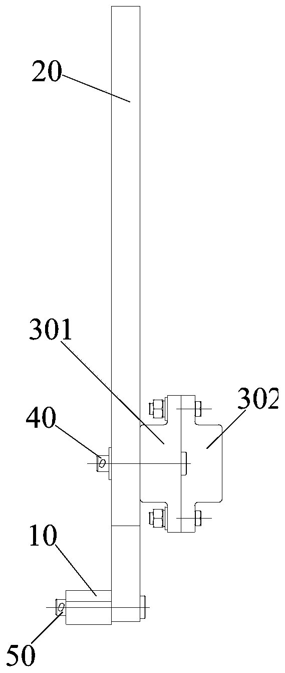
[0052] The clamping part is a clamp 30, and the clamp 30 includes a left half clamp 301 and a right half clamp 302 which can be detachably connected. The groove 303 of the connecting rod end, such as figure 1 , figure 2 , image 3 , Figure 5 , Figure 6 , Figure 9 , Figure 10 and Figure 11 shown.
[0053] The clamping part is a clamp 30, and the clamp 30 includes a left half clamp 301 and a right half clamp 302, and the inner sides of the left half clamp 301 and the right half clamp 302 are provided with grooves 303, and the grooves 303 and the concrete The connecting rod end of the piston 2 is suitable for clamping the concrete piston. When the clamp 30 is assembled with the concrete piston, it is only necessary to clamp the groove 303 of the left half clamp 301 and the right half clamp 302 to the concrete piston 2. At the end of the connecting rod, just connect the left half clamp 301 and the right half clamp 302. The clamp 30 is connected relatively firmly, and...
Embodiment 2
[0057] Embodiment 2 (not shown in the figure)
[0058] The difference from Embodiment 1 is that one end of the left half clamp 301 and one end of the right half clamp 302 are hinged to each other, and the other end of the left half clamp 301 and the other end of the right half clamp 302 are connected by bolts .
[0059] One end of the left half clamp 301 and the right half clamp 302 is hinged by a hinge, so the left half clamp 301 and the right half clamp 302 can rotate relatively, and the other ends are connected by bolts, the left half clamp 301, the right half clamp When the hoop 302 is assembled with the concrete piston, the left half hoop 301 and the right half hoop 302 do not need to be repeatedly connected through the hinged end, and the connecting rod end of the concrete piston 2 only needs to be placed on the left half hoop 301 and the right half hoop 301. In the groove 303 of the half clamp 302, the other end can be fixedly connected by bolts, which further improves...
Embodiment 3
[0062] Embodiment three (not shown in the figure)
[0063] The difference from Embodiment 1 and Embodiment 2 is that the concrete piston connector includes a mounting plate and a plurality of movable grapples arranged on the mounting plate, and the multiple movable grapples are distributed at intervals along the circumferential direction of the mounting plate.
[0064] The concrete piston connector includes a mounting plate and multiple movable grapples. The multiple movable grapples are all facing the concrete piston and can be hooked with the connecting rod end of the concrete piston 2 to play the role of multi-point limit. The movable grapples are arranged on the installation plate and distributed at intervals along the circumferential direction of the installation plate, so that multiple movable grapples can be hooked at multiple points along the circumferential direction of the concrete piston, effectively improving the reliability of the connection between the movable gra...
PUM
 Abstract
Description
Claims
Application Information
 - R&D
- Intellectual Property
- Life Sciences
- Materials
- Tech Scout
- Unparalleled Data Quality
- Higher Quality Content
- 60% Fewer Hallucinations
Browse by: Latest US Patents, China's latest patents, Technical Efficacy Thesaurus, Application Domain, Technology Topic, Popular Technical Reports.
© 2025 PatSnap. All rights reserved.Legal|Privacy policy|Modern Slavery Act Transparency Statement|Sitemap|About US| Contact US: help@patsnap.com


