A mechanical arm assembly for automated production

A technology of mechanical arms and components, applied in the field of automation, can solve the problems of short service life of arm end joints, unable to adjust the position, unable to adjust the horizontal direction, etc., and achieve the effect of good connection effect, good firm performance and good stability.

Active Publication Date: 2021-09-07
浙江鑫佳硕科技有限公司
View PDF8 Cites 1 Cited by
  • Summary
  • Abstract
  • Description
  • Claims
  • Application Information

AI Technical Summary

Problems solved by technology

[0004] The purpose of the present invention is to provide a mechanical arm assembly for automatic production, which can solve the problem that the position of the traditional mechanical arm assembly cannot be adjusted in the horizontal direction after being fixed, resulting in a relatively limited range of use of the mechanical arm. The use environment is adjusted horizontally, and the connection means of the support arm and the arm of the existing mechanical arm assembly is relatively simple. The support arm and the arm are prone to loosening when used for a long time. When it is larger, other joints cannot better share the arm end joints, resulting in the long-term excessive force on the arm end joints and easy damage, which makes the service life of the arm end joints shorter. After the components are installed and fixed, the adjustment of the lateral position of the mechanical arm components is realized, which is convenient to adapt to different working areas, and can effectively reduce the pressure on the arm end joints when the arm end joints are clamping objects, and play a better role. The protective effect of the arm and the arm can also be reinforced, so that the firmness between the arm and the arm is better, and the looseness between the arm and the arm is effectively avoided.

Method used


Image

  • A mechanical arm assembly for automated production
  • A mechanical arm assembly for automated production
  • A mechanical arm assembly for automated production

Examples


Embodiment Construction

[0039] The technical solutions of the present invention will be clearly and completely described below in conjunction with the embodiments. Apparently, the described embodiments are only some of the embodiments of the present invention, not all of them. Based on the embodiments of the present invention, all other embodiments obtained by persons of ordinary skill in the art without creative efforts fall within the protection scope of the present invention.

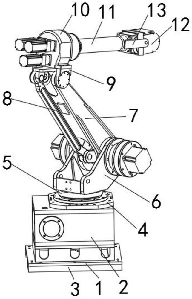
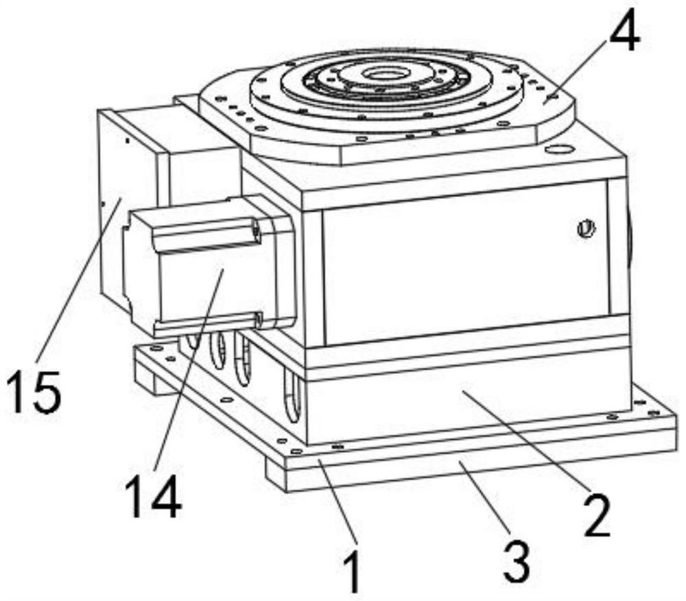
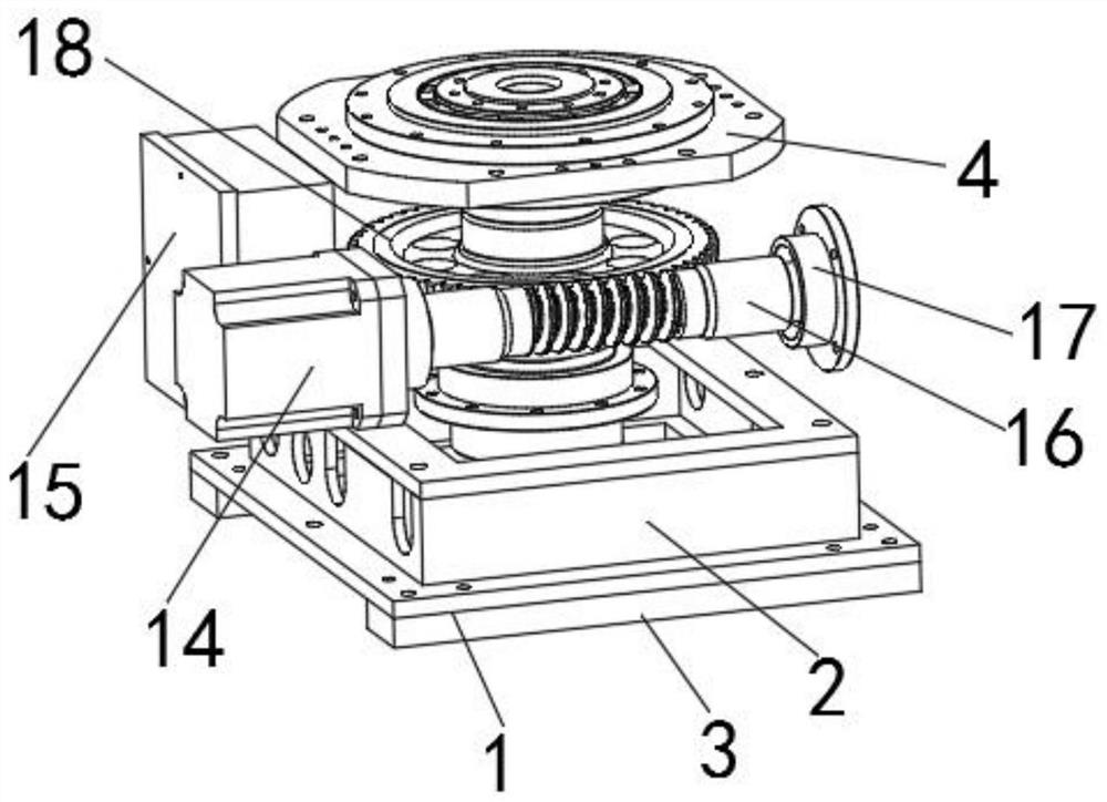
[0040] see Figure 1-8 As shown, a mechanical arm assembly for automatic production includes a base plate 1, a box body 2 is fixedly installed on the upper surface of the base plate 1, and a translation frame 3 is fixedly installed on the lower surface of the base plate 1, and a fixed frame 3 is fixedly installed on the upper surface of the box body 2. disc 4, and the upper surface of the fixed disc 4 is connected with a drive disc 5, the upper part of the drive disc 5 is connected with a short arm 6, and the inner side of ...


PUM


Abstract

The invention discloses a manipulator assembly for automatic production, comprising a bottom plate, a box body is fixedly installed on the upper surface of the bottom plate, a translation frame is fixedly installed on the lower surface of the bottom plate, and a fixed plate is arranged on the upper surface of the box body , and the upper surface of the fixed disk is connected with a driving disk, the upper part of the driving disk is connected with a short arm, and the inner side of the short arm is connected with a support arm, and one side of the support arm is provided with a connecting arm; the invention discloses a A mechanical arm assembly for automatic production, the invention can realize the adjustment of the lateral position of the mechanical arm assembly after the mechanical arm assembly is installed and fixed, which is convenient to adapt to different working areas, and can be effective when the arm end joints clamp objects It can reduce the pressure on the joints at the end of the arm and play a better protective role. It can also reinforce the support arm and the arm rod, making the firmness between the support arm and the arm rod better, effectively avoiding the There is looseness between the arms.

Description

technical field [0001] The invention relates to the field of automation, in particular to a mechanical arm assembly for automatic production. Background technique [0002] The robotic arm is a machine that replaces the human arm for processing, and can be used with a single-chip microcomputer to realize automatic control, complete processing operations in an orderly manner, and complete operations such as clamping, handling, and spot welding of the product to be processed. Compared with manual , the mechanical arm has high working efficiency, can withstand greater working intensity, and makes fewer mistakes during work, and can complete the processing of products accurately and quickly. It is one of the important machines that replace manual processing. , most of the existing manipulators have good working results, but there are also certain deficiencies that need to be improved, and it is believed that they will be further developed. [0003] Although the existing manipula...

Claims


Application Information

Patent Timeline
Patent Type & Authority Patents(China)
IPC IPC(8): B25J9/12B25J17/02B25J19/00
Inventor 张鸿恺伍超陈杰张振亚李杨徐勇谢陈磊
Owner 浙江鑫佳硕科技有限公司
Why Eureka
Try Eureka