
Energy-mixing atomization device

An atomization device and energy mixing technology, which is applied in the directions of household heating, space heating and ventilation details, heating methods, etc. problems, to achieve the effect of improving cleanliness, wide application range, and speeding up evaporation

Pending Publication Date: 2019-05-17
GUANGDONG FLEXWARM ADVANCED MATERIALS & TECH CO LTD
View PDF0 Cites 2 Cited by
  • Summary
  • Abstract
  • Description
  • Claims
  • Application Information

AI Technical Summary

Problems solved by technology

[0002] An air humidifier is a household appliance used to increase indoor humidity. The traditional air humidifier directly converts water into cold / hot steam through a steam generator installed inside the body and then outputs it to the room. However, due to this type of air humidification It is difficult to control the temperature of the cooling and heating water body of the device, resulting in an error between the final output steam temperature and the set temperature value; and in order to overcome the above shortcomings, ultrasonic humidification devices have appeared on the market. Ultrasonic humidification devices mainly use high-frequency oscillations , and then through the high-frequency vibration of the atomizing sheet, the water with a certain temperature in the humidifier is thrown off the water surface to produce elegant water mist and is output to the room to achieve the purpose of air humidification, but the steam particles generated by the ultrasonic humidifier cannot reach At the nanometer level, it is easy to be directly inhaled into the lungs by the human body, causing discomfort and bad for health

Method used


Image

  • Energy-mixing atomization device
  • Energy-mixing atomization device
  • Energy-mixing atomization device

Examples


Embodiment approach

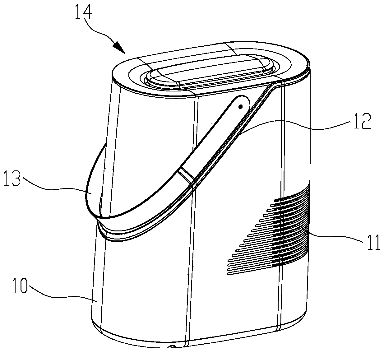
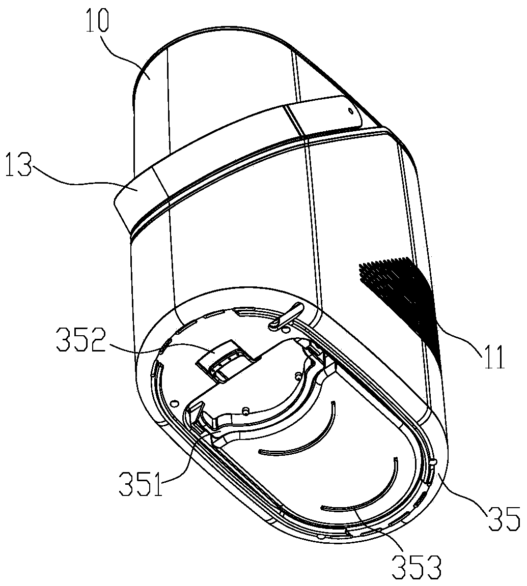
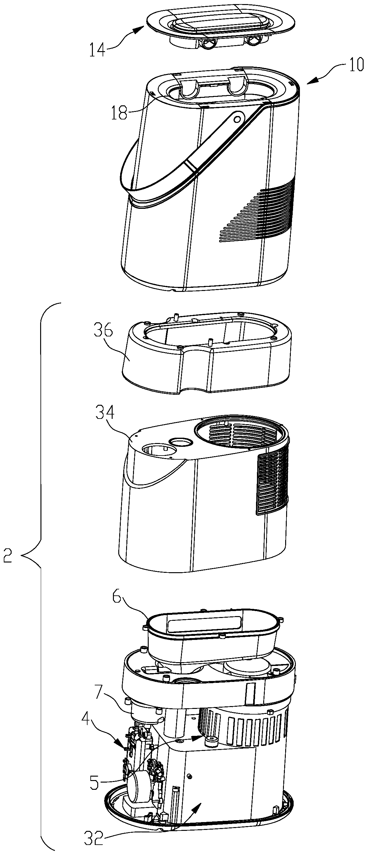
[0034] see Figure 1 to Figure 3 , This is a mixed-energy atomization device according to the embodiment, including a body 2 , a control device (not shown in the figure), a housing 10 and an upper cover 14 .

[0035] The body 2 is provided with a first atomizing mechanism 5 , a second atomizing mechanism 4 and a water adding and exhausting mechanism 6 .

[0036] see Figure 4 to Figure 5 , the first atomization mechanism 5 includes a water storage chamber 32 , a molecular sieve 31 and an atomizing fan 51 , the molecular sieve 31 is installed in the water storage chamber 32 , and the atomizing fan 51 is used to generate an airflow passing through the molecular sieve 31 .

[0037] In order to increase the amount of mist generated by the atomizing fan 51 , the molecular sieve 31 has a hollow columnar structure, and the atomizing fan 51 is arranged at the upper center of the molecular sieve 31 .

[0038] see Figure 4 to Figure 5 , the second atomizing mechanism 4 includes a st...


PUM


Abstract

The invention provides an energy-mixing atomization device. The energy-mixing atomization device comprises a machine body, wherein the machine body is internally provided with a first atomization mechanism, a second atomization mechanism and a water adding and discharging mechanism; The first atomizing mechanism comprises a water storage cavity, a molecular sieve and an atomization fan, wherein the molecular sieve is installed in the water storage cavity, and the atomization fan is used for generating gas flow passing through the molecular sieve; The second atomization mechanism comprises a steam generation device, and the water inlet end of the steam generation device is connected with the water storage cavity; and the steam outlets of the first atomization mechanism and the second atomizing mechanism communicated with the water storage cavity to form a three-way structure. Compared with the prior art, the mixed atomization device can adjust the temperature of output atomized water.

Description

technical field [0001] The invention relates to the field of air humidification devices, in particular to a hybrid energy atomization device. Background technique [0002] An air humidifier is a household appliance used to increase indoor humidity. The traditional air humidifier directly converts water into cold / hot steam through a steam generator installed inside the body and then outputs it to the room. However, due to this type of air humidification It is difficult to control the temperature of the cooling and heating water body of the device, resulting in an error between the final output steam temperature and the set temperature value; in order to overcome the above shortcomings, ultrasonic humidification devices have appeared on the market, and ultrasonic humidification devices mainly use high-frequency oscillations , and then through the high-frequency vibration of the atomizing sheet, the water with a certain temperature in the humidifier is thrown off the water surf...

Claims


Application Information

Patent Timeline
Patent Type & Authority Applications(China)
IPC IPC(8): F24F6/12F24F6/00F24F11/89F24F13/00F24F13/20A61L2/10
Inventor 黄伟聪蔡自光郑智文
Owner GUANGDONG FLEXWARM ADVANCED MATERIALS & TECH CO LTD
Learn More