Launching method of rocket weapon or launcher launching system

A rocket weapon and launch system technology, which is applied in the field of box-type rocket launchers, can solve the problems of long development period, unguaranteed, and short development period of rocket launch vehicles, and achieve shortened development period, guaranteed development progress, and strong environmental adaptability Effect

Active Publication Date: 2022-03-25
湖北航天飞行器研究所
View PDF8 Cites 0 Cited by
  • Summary
  • Abstract
  • Description
  • Claims
  • Application Information

AI Technical Summary

Problems solved by technology

[0003] However, in recent years, rocket weapon systems are faced with increasingly urgent requirements for low funding, short cycle time, and high reliability in the development process. Therefore, some types of weapon systems will have a long development cycle for rocket launchers or insufficient funds in the initial stage of development. Timely output cannot be guaranteed due to various reasons, which will affect the flight test launch mission of the box rocket, which in turn will affect the model project approval or contract bidding
[0004] Therefore, the traditional box-type rocket launch vehicle cannot meet the requirements of low R&D and production costs, short R&D period and high reliability in reality.

Method used


Image

  • Launching method of rocket weapon or launcher launching system
  • Launching method of rocket weapon or launcher launching system
  • Launching method of rocket weapon or launcher launching system

Examples


Embodiment 1

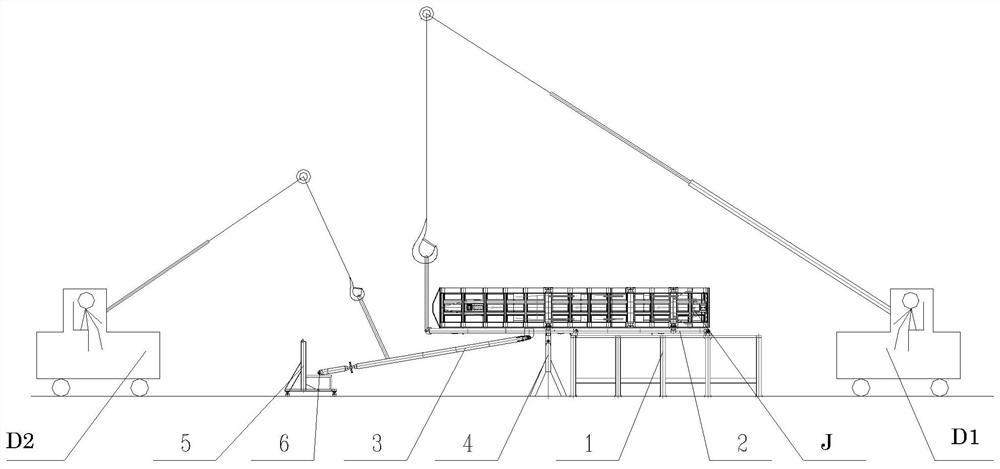
[0053] Such as figure 1 Shown, rocket weapon or launcher launch system, including:

[0054] The base platform 1 is fixed on the ground when in use.

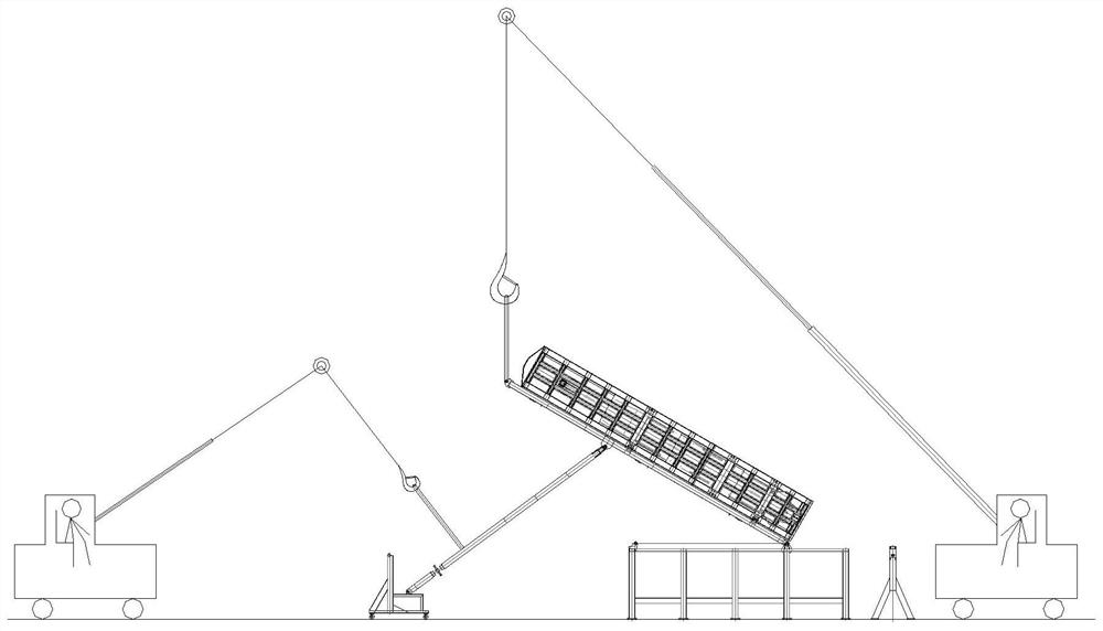
[0055] Erecting platform 2, one end is rotatably fixed on the fixed position of base platform;

[0056] Oblique supporting platform 3, one end is rotatably connected with the erecting platform, and the other end is a free end,

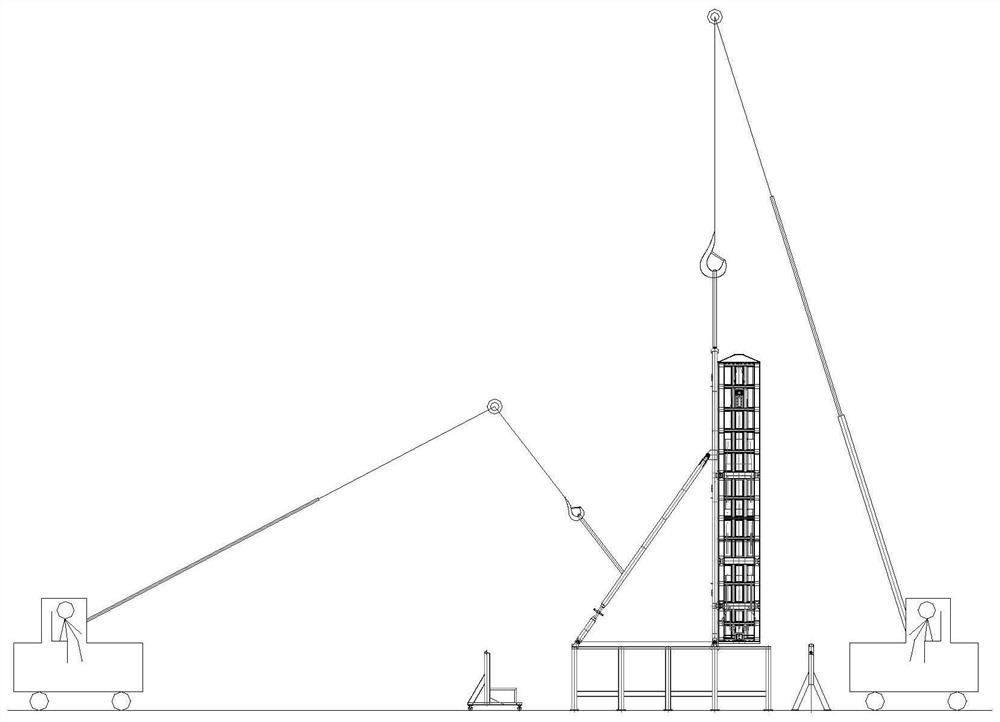
[0057] Wherein, a locking structure is provided at a position away from the fixed position of the base platform,

[0058] When the erecting platform is erected and rotated to a predetermined angle, the free end of the inclined support platform is fixed and locked on the base platform through the locking structure arranged on the base platform.

Embodiment 2

[0060] On the basis of Embodiment 1, as an optimization, one end of the erecting platform is fixed on the fixed position of the base platform by a fixed pin; and / or,

[0061] One end of the inclined support platform is rotatably connected with the erecting platform through a pin shaft;

[0062] and / or,

[0063] The locking structure is a pin hole arranged on the base platform,

[0064] When fixing, the fixed pin shaft passes through the pin shaft hole, and the free end of the inclined support platform is connected and fixed at the pin shaft hole through the fixed pin shaft 6 .

[0065] By using the solution of the fixed pin shaft, the structure is simple, the design is convenient for rapid design, and the design and manufacturing time is shortened.

Embodiment 3

[0067] On the basis of the above-mentioned embodiment 1-2, the free end of the oblique support platform is provided with a double-ended screw, and the hole on the oblique support platform can be aligned with the pin shaft hole through the double-ended screw for installation of the fixed pin shaft.


PUM


Abstract

The rocket weapon or launcher launch system is characterized in that it includes: a base platform, which is fixed on the ground when in use; an erecting platform, one end of which is rotatably fixed on a fixed position of the base platform; The erecting platform is rotatably connected, and the other end is a free end, wherein a locking structure is provided at a position away from the fixed position of the base platform, and when the erecting platform is erected and rotated to a predetermined angle, the free end of the inclined support platform It is fixed and locked on the base platform by a locking structure arranged on the base platform. The invention adopts a purely mechanical structure scheme to complete the design of the box-type rocket launching device, solves the problem of launching tasks under the conditions of low-cost, fast-paced and high-reliability development, has the characteristics of easy operation, low cost, and high strength, and broadens the range of box-type rocket launchers. Type of rocket launch mode.

Description

technical field [0001] The invention belongs to rocket launching technology, and specifically designs a box-type rocket launching device. Background technique [0002] The launch methods used for reverse thrust jet launchers such as box-type rockets or missiles mostly use the launch method of rocket launch vehicles. At the same time, the rocket launch vehicle has the outstanding advantages of high automation and high launch accuracy, so the box-type rocket launch vehicle is a conventional equipment that must be designed during the rocket development process. [0003] However, in recent years, rocket weapon systems are faced with increasingly urgent requirements for less funding, shorter cycle times, and higher reliability during the development process. Therefore, some types of weapon systems will suffer from the long development cycle of rocket launchers or insufficient funds in the initial stage of development. Timely output cannot be guaranteed due to various reasons, wh...

Claims


Application Information

Patent Timeline
Patent Type & Authority Patents(China)
IPC IPC(8): F41F3/04
Inventor 李盛薛士明蔺法鹏刘斌谢永刚
Owner 湖北航天飞行器研究所
Why Eureka
Try Eureka