
A photoelectric anti-collision device

A photoelectric, anti-collision technology, applied in the direction of instruments, manufacturing stator/rotor body, alarm, etc., can solve problems such as difficulties and poor lighting, achieve reliable detection of collisions, avoid equipment damage, and save labor costs.

Active Publication Date: 2020-08-07
CHINA GENERAL NUCLEAR POWER OPERATION +2
View PDF4 Cites 0 Cited by
  • Summary
  • Abstract
  • Description
  • Claims
  • Application Information

AI Technical Summary

Problems solved by technology

At a length of 1 meter, with poor lighting, it is more difficult to observe whether a 2-3mm air gap has changed to a dangerous level (such as 1mm), and whether a collision has occurred

Method used


Image

  • A photoelectric anti-collision device
  • A photoelectric anti-collision device
  • A photoelectric anti-collision device

Examples


Embodiment Construction

[0030] In order to have a clearer understanding of the technical features, purposes and effects of the present invention, the specific implementation manners of the present invention will now be described in detail with reference to the accompanying drawings.

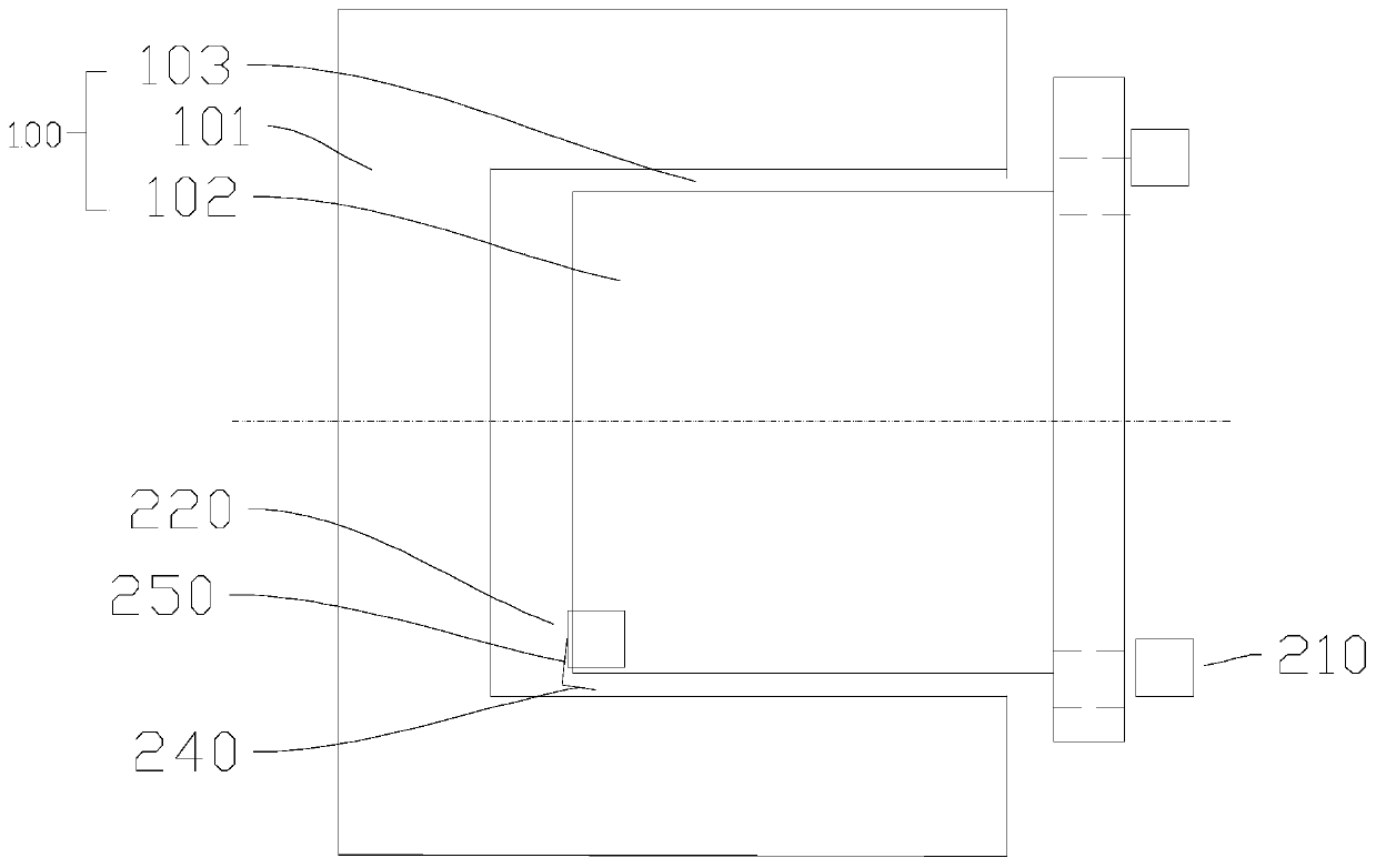
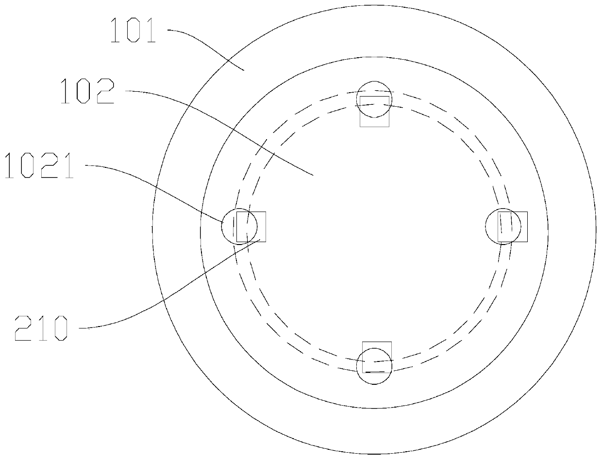
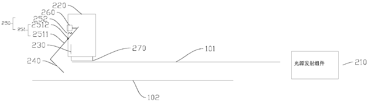
[0031] Figure 1 to Figure 3 A preferred embodiment of the photoelectric anti-collision device of the present invention is shown. The photoelectric anti-collision device can be used for the maintenance of the exciter 100 . The exciter 100 includes an armature 101 and a stator 102; when the exciter 100 is overhauled and the stator 102 is pulled through the armature 101, the armature 101 collides with the stator 102, and the outer wall of the stator 102 collides with the armature. A gap is left between the inner side walls of the stator 101 to form an air gap 103 ; the air gap 103 is opposite to the observation hole 1021 provided on the end surface of the stator 102 away from the armature 101 . By adopting the photoelec...


PUM


Abstract

The present invention relates to a photoelectric anti-collision apparatus. The anti-collision apparatus includes a light source emitting component, a mounting box, a light source receiving component,a light reflecting component, a linkage mechanism, a touch unit, and a control unit. The light source emitting component is disposed on one side of a stator away from an armature. The mounting box ismounted on the inner side wall of the stator. The light source receiving component is mounted in the mounting box, and the light reflecting component is disposed at one end of an air gap away from anobservation hole. The touch unit is disposed on the inner side of the mounting box. The linkage mechanism is rotatably connected to the mounting box, one end of the linking mechanism is inserted intothe inner side of the mounting box and opposite to the touch unit, and the other end extends toward the air gap to connect to the light reflecting component to drive the light reflecting component torotate and form a linkage with the touch unit. The control unit is connected to the touch unit and the light source receiving component. The photoelectric anti-collision apparatus is used, an operatordoes not need to observe the observation hole in real time, so that labor costs can be saved, collision can be reliably detected, safety of pumping through the stator can be improved, and damage to device can be avoided.

Description

technical field [0001] The invention relates to the technical field of electrical maintenance, and more specifically relates to a photoelectric anti-collision device. Background technique [0002] The stator of the exciter needs to be pulled out for maintenance during the overhaul of the nuclear power plant. The stator of the exciter is a drum-packed structure, which is installed inside the armature, and the armature is also a drum-packed structure. The air gap between the stator and the armature is only 2-3mm, and the total length of the stator is about 1 meter. During the pumping and threading process, personnel are required to observe the air gap through the measuring hole. Adjust to avoid collision between the outer circle of the stator and the inner circle of the armature. If the collision between the two is not found in time and the trolley continues to be pulled, both the armature and the stator may be severely damaged. [0003] The current difficulty is that four p...

Claims


Application Information

Patent Timeline
Patent Type & Authority Patents(China)
IPC IPC(8): H02K15/02G08B21/18
Inventor 王建涛
Owner CHINA GENERAL NUCLEAR POWER OPERATION
Learn More