
Plant ash removing device

A plant and ash collection technology, applied in suction nozzles, cleaning equipment, vacuum cleaners, etc., can solve the problems of high labor intensity, deterioration of production environment, and ash on the ground, and achieve good cleaning effect, wide cleaning range and strong adaptability. Effect

Active Publication Date: 2019-05-21
王铁霞
View PDF6 Cites 5 Cited by
  • Summary
  • Abstract
  • Description
  • Claims
  • Application Information

AI Technical Summary

Problems solved by technology

However, when the amount of dust is large, the shortcomings of low cleaning efficiency and weak cleaning effect of the broom are obvious, and the labor intensity of workers cleaning is also very high.
If the dust in the factory building is not cleaned up in a timely and effective manner, it will easily lead to dust and scale accumulation on the ground, which will further lead to the deterioration of the production environment

Method used


Image

  • Plant ash removing device
  • Plant ash removing device
  • Plant ash removing device

Examples


Embodiment 1

[0033] Example 1: as Figure 1 to Figure 4 shown,

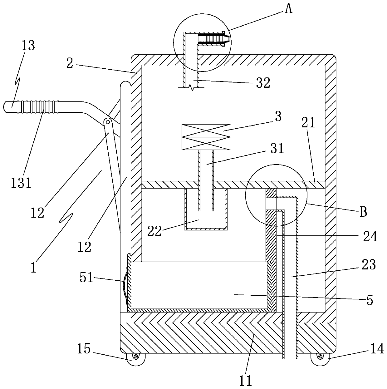
[0034] An ash removal device for a factory building, comprising a cart 1, a casing 2 disposed on the cart, a dust suction motor 3 disposed in the casing, and a diaphragm 21 disposed in the casing;

[0035] The diaphragm divides the interior of the casing into an upper cabin and a lower cabin, the vacuuming motor is located in the upper cabin, and the lower cabin is provided with a filter cartridge 22 with an upper end open, and the upper end of the filter cartridge is sealed with the diaphragm. The board is provided with an air inlet pipe 31 passing through the diaphragm, the upper end of the air inlet pipe is connected to the air inlet end of the vacuum motor, the lower end of the air inlet pipe is located in the filter cartridge, and the casing is provided with a ash cleaning port that communicates with the lower engine room and a ash cleaning door that can cover the ash cleaning port. The casing is provided with an exhaus...

Embodiment 2

[0043] Example 2: Based on Example 1, as Figure 5 to Figure 10 shown,

[0044] The upper engine room is provided with a switching and cleaning structure, which includes a transverse sleeve 61, a transverse core column 62 that is slidingly and sealedly matched with the transverse sleeve, an inner rod 63 connected to the transverse core column, and an inner rod slidably connected to the casing. The seat plate 64 and the switching cylinder 65 fixed with the diaphragm, the inner rod is connected to the inner seat plate, and the inner seat plate is provided with a number of outer rods 641 which pass through the casing and are slidingly and sealingly matched with the casing, and the outer rods are arranged in parallel , the outer casing is provided with a touch wall plate 66 for contacting the wall, and the touch wall plate is connected to each outer rod;

[0045] The switching cylinder is provided with a switching master piston 651 which is slidingly and sealingly matched with th...


PUM


Abstract

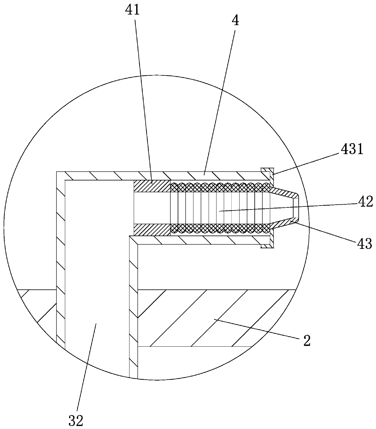
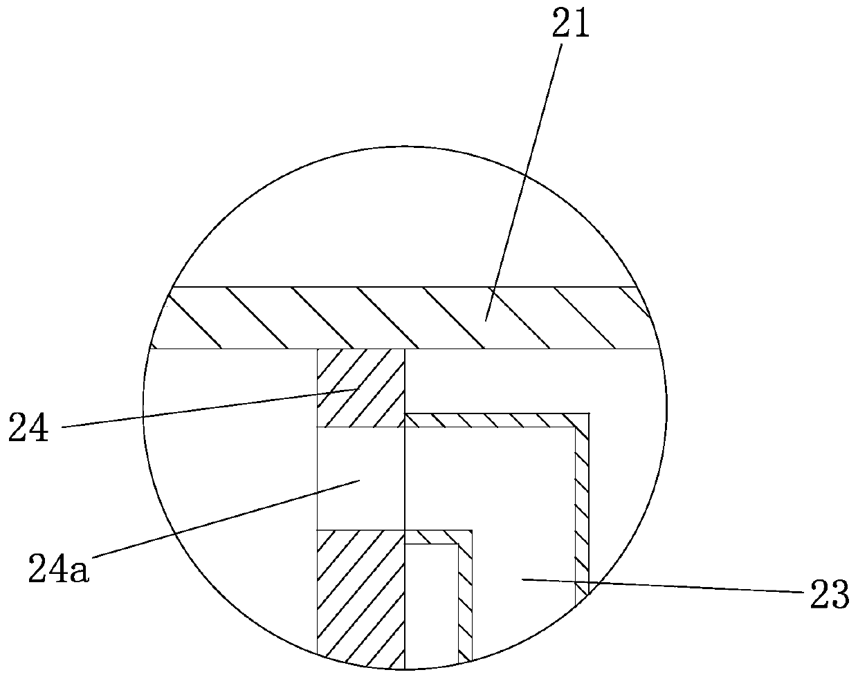
The invention discloses a plant ash removing device. The plant ash removing device comprises a cart, a machine shell and a dust collection motor; a filtering drum is arranged in a lower cabin, an airexhausting pipe is arranged on the machine shell, and a fixed pipe is arranged on the air exhausting pipe; an inner join pipe, an elastic corrugated pipe and a main gas ejector pipe which are sequentially communicated are arranged on the fixed pipe, an outer cover frame is arranged on the main gas ejector pipe, and is clamped to the fixed pipe, the inner join pipe and the elastic corrugated pipe are located in the fixed pipe, and the outer side wall of the inner join pipe and the inner side wall of the fixed pipe are fixedly sealed; a dust collection pipe penetrating through the bottom of themachine shell and a cart plate is arranged on the machine shell, the upper end of the dust collection pipe is located in the lower cabin, a vertical partition plate is arranged in the lower cabin, theinside of the lower cabin is divided by the vertical partition plate into a dust collecting cavity and a working cavity, a vertical plate hole is formed in the vertical partition plate, the upper endof the dust collection pipe is communicated with the vertical plate hole, and an ash cleaning opening is communicated with the dust collecting cavity. The plant ash removing device has the advantagesthat dust collection, isolation and air exhausting functions can be automatically completed, a user only needs to conduct pushing operation, moving cleaning can be achieved, dead angles can be injected through clean air, the cleaning range is wide, and the adaptability is high.

Description

technical field [0001] The invention belongs to the technical field of dust removal, ash removal and air purification, in particular to a workshop ash removal device. Background technique [0002] In the production process, a lot of dust is often generated in the workshop and workshop, and a tidy and clean factory production environment is what everyone needs. When the amount of dust is small, just use a broom to clean it up. However, when the amount of dust is large, the shortcomings of low cleaning efficiency and weak effect of the broom are obvious, and the labor intensity of cleaning is also very large. However, if the dust in the workshop is not cleaned up in a timely and effective manner, it will easily lead to ash and fouling on the ground, which will further lead to the deterioration of the production environment. SUMMARY OF THE INVENTION [0003] The invention provides a plant ash removal device, which can automatically complete the functions of vacuuming, isola...

Claims


Application Information

Patent Timeline
Patent Type & Authority Applications(China)
IPC IPC(8): A47L5/28A47L7/00A47L9/00A47L9/06
Inventor 王铁霞
Owner 王铁霞
Learn More