

Reaction kettle and cleaning method thereof
A reaction kettle and cleaning tube technology, applied in cleaning methods and appliances, chemical instruments and methods, chemical/physical/physical chemical fixed reactors, etc., can solve multiple cleaning dead ends, high labor intensity, troublesome cleaning, etc. problems, to achieve the effect of reducing cleaning dead angle, improving cleaning speed, and avoiding damage or deformation of the upper cover
- Summary
- Abstract
- Description
- Claims
- Application Information
AI Technical Summary
Problems solved by technology
Method used
Image

Examples
Embodiment 1
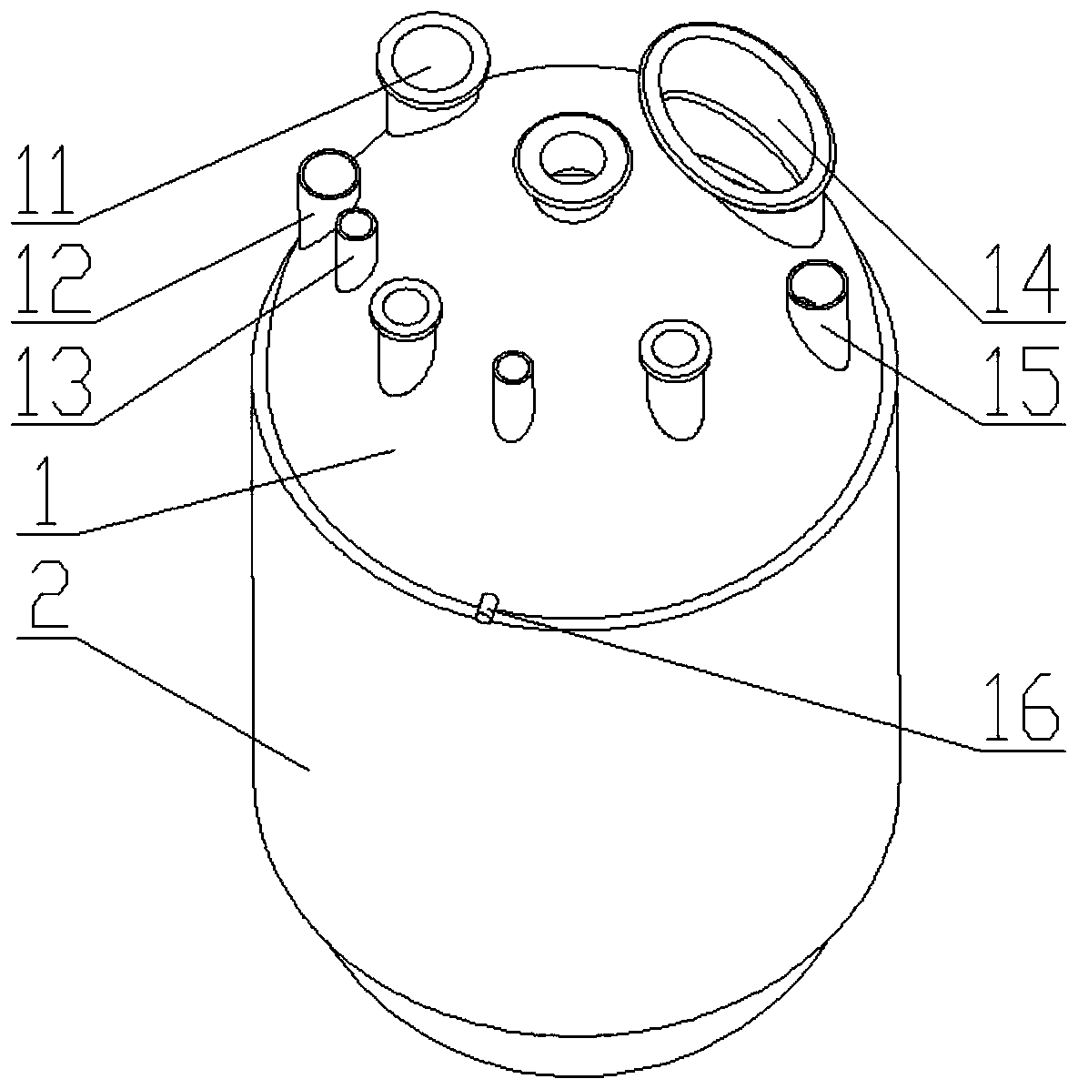
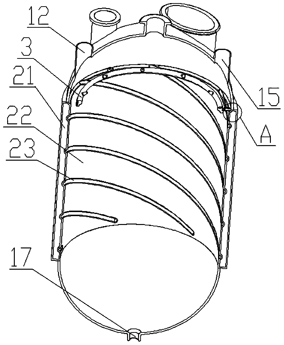
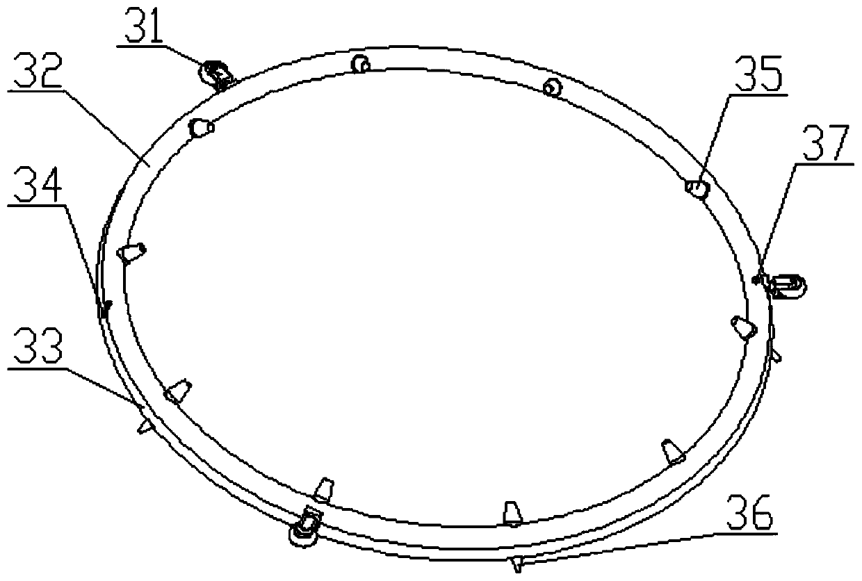
[0031] like Figure 1 to Figure 5 Shown; A kind of reactor, comprises tank body 2 and the loam cake 1 that is connected on the tank body 2, described loam cake 1 is provided with feed port 11, liquid inlet port 13 and maintenance port 14, and described tank body 2. It includes a heating wall 22, a heating jacket 21 and a tank bottom connected to the bottom of the heating wall 22. The bottom of the tank is provided with a discharge port 17, and the heating jacket 21 is set on the heating wall 22; it also includes cleaning Device 3, the upper cover 1 is symmetrically provided with a left pipe inlet 12 and a right pipe inlet 15, and the left pipe inlet 12 and the right pipe inlet 15 are provided with a sealing cover; the heating wall 22, etc. There are at least three spiral heating concave rails 23 for positioning and sliding of the cleaning device 3; The ring 32 is arranged above the lower cleaning pipe ring 33, and the upper cleaning pipe ring 32 is provided with at least 3 un...
Embodiment 2
[0034]On the basis of Embodiment 1, the upper cover 1 is provided with at least one locking bolt 16, and the cleaning device 3 is locked by the locking bolt 16; the spraying direction of the upper track nozzle 35 forms an included angle with the horizontal line A and forms an angle B with the axis of the tank body 2, and the lower track nozzle 36 forms an angle C with the horizontal line, the angle A is from 5 degrees to 60 degrees, and the angle B is from 1 degree to 60 degrees. 5 degrees, the degree of the angle C is 45 degrees to 135 degrees; the lower cleaning pipe ring 33 is equidistantly provided with at least 20 lower trajectory nozzles 36, and the angle C of the lower trajectory nozzles 36 ranges from small to The larger ones increase in the same order; the upper cleaning tube ring 32 is equidistantly provided with at least 20 upper track nozzles 35, and the included angle A of the upper track nozzles 35 increases in equal order from small to large; the spiral heating c...
Embodiment 3
[0037] Adopt the cleaning method of the reactor of embodiment 2, comprise the following steps:
[0038] S1. Open the sealing covers on the left pipe inlet 12 and the right pipe inlet 15, respectively install hollow screws on the water inlet 34 of the lower circle and the water inlet 37 of the upper circle, and connect the two hollow screws to the high-pressure water pump through the high-pressure water pipe Control the switching switches of the two high-pressure water pipes through the three-way valve, adjust the pressure valves on the two high-pressure water pipes to control the pressure in the upper cleaning pipe ring 32 and the lower cleaning pipe ring 33; the upper cleaning pipe ring 32 and the lower cleaning pipe ring 33 The water pressure inside is controlled at 200MPa to 320MPa; to control the water pressure at 200MPa to 320MPa depends on the number of nozzles, and the number of nozzles is controlled at 20-40, too many nozzles will affect the water outlet speed.
[0039...
PUM
| Property | Measurement | Unit |
|---|---|---|
| Degree | aaaaa | aaaaa |
| Degree | aaaaa | aaaaa |
| Degree | aaaaa | aaaaa |
Abstract
Description
Claims
Application Information