Distribution box preset hole breaking device

A technology of presetting holes and distribution boxes, which is applied in the field of transformation and distribution network, can solve problems such as danger, achieve high installation efficiency and achieve the effect of angle adjustment

Pending Publication Date: 2019-05-21
GUANGDONG POWER GRID CO LTD +1
View PDF0 Cites 0 Cited by
  • Summary
  • Abstract
  • Description
  • Claims
  • Application Information

AI Technical Summary

Problems solved by technology

Based on different requirements, an easy-to-remove cover plate with a preset hole is generally installed on the through hole, and generally when dismantled, it will be removed by hammering or using pliers according to different actual conditions. , when the line is charged, the above two removal methods are relatively dangerous, especially at the cable joint near the primary live side, so it is necessary to develop a safer preset hole removal device

Method used


Image

  • Distribution box preset hole breaking device
  • Distribution box preset hole breaking device
  • Distribution box preset hole breaking device

Examples


Embodiment 1

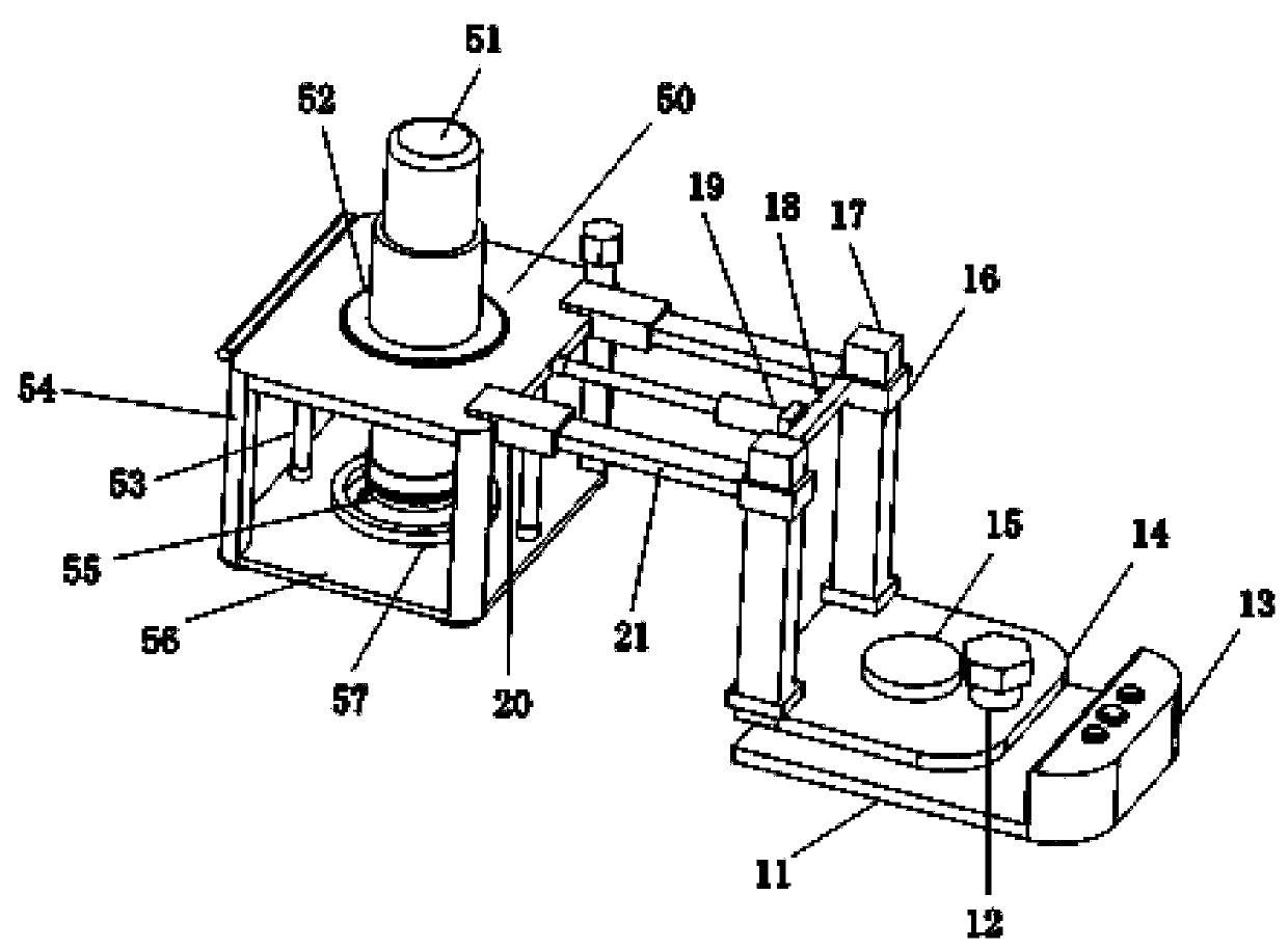
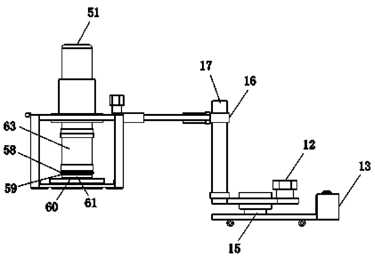
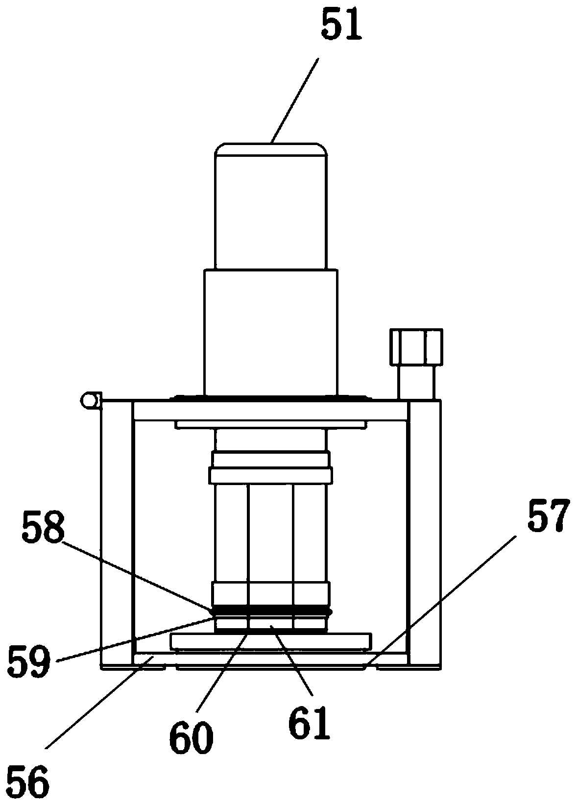
[0038] like Figure 1 to Figure 5 As shown, the embodiment of the present invention provides a device for breaking a preset hole in a distribution box, including an auxiliary adjustment component and a breaking component, and the preset hole is broken through the auxiliary adjustment component and the breaking component.

[0039] Specifically, the auxiliary adjustment assembly includes a main base 11, an intermediate turntable 14 arranged on the main base 11 and rotatably connected to it, a vertical guide rod 17 fixedly connected to the middle turntable 14, and a sliding connection set on the The vertical sliding sleeve 16 on the vertical guide rod 17, the horizontal sliding rod 21 fixedly connected to the vertical sliding sleeve 16, and the sliding connection sleeve are arranged on the side of the horizontal sliding rod 21 away from the vertical sliding sleeve 16. The horizontal sliding sleeve 20 on one end and the horizontal adjustment push mechanism 19; the breaking assembl...

Embodiment 2

[0042] On the basis of Embodiment 1, moving wheels are provided under the main base 11 to facilitate the movement of the entire breaking device.

Embodiment 3

[0044] On the basis of Embodiment 1, the auxiliary adjustment assembly also includes an adjustment shaft 15, and a rotation shaft hole is provided on the intermediate turntable 14, and the main base 11 and the intermediate rotation shaft pass through the adjustment shaft 15 and the rotation shaft hole. The fit and rotation connection between them. An adjustment knob 12 is provided on one side of the middle turntable 14 , and the adjustment knob 12 is set on the middle turntable 14 for adjusting the rotation between the middle turntable 14 and the main base 11 . This embodiment discloses a specific rotational connection mode between the intermediate turntable 14 and the main base 11 .


PUM


Abstract

The invention discloses a distribution box preset hole breaking device comprising an auxiliary adjusting component and a breaking component. The auxiliary adjusting component comprises a main base, anintermediate rotary disc, a vertical guiding rod, a vertical sliding sleeve, a horizontal sliding rod, a horizontal sliding sleeve and a horizontal adjustment pushing mechanism; the breaking component comprises a fixing plate and a vertical transmission mechanism which is rotatably connected and mounted on the fixing plate, and one end of the vertical transmission mechanism is in driven connection with an outer ring cutter for breaking a distribution box preset hole; the horizontal sliding sleeve is also fixedly connected to the fixing plate; and the fixed end of the horizontal adjustment pushing mechanism is fixedly connected to the vertical sliding sleeve, and the telescopic end of the horizontal adjustment pushing mechanism is fixedly connected to the fixing plate. Compared with a conventional breaking mode, the breaking device provided by the embodiment is safer and more convenient, the installation efficiency is higher, and the impact on overall operation of a distribution box islower.

Description

technical field [0001] The invention relates to the technical field of transformation and distribution networks, in particular to a device for removing preset holes in a distribution box. Background technique [0002] In the installation and assembly of the distribution box, a number of through holes are opened at the top or bottom of the distribution box to facilitate the passing of the cables so as to facilitate the passage of the cables and to space the cables. Based on different requirements, an easy-to-remove cover plate with a preset hole is generally installed on the through hole, and generally when dismantled, it will be removed by hammering or using pliers according to different actual conditions. , when the line is charged, the above two removal methods are relatively dangerous, especially at the cable joint near the primary live side, so it is necessary to develop a safer preset hole removal device. Contents of the invention [0003] The purpose of the present ...

Claims


Application Information

Patent Timeline
Patent Type & Authority Applications(China)
IPC IPC(8): B23D79/00B23P23/04
Inventor 陈壮奕陈利昭罗锦填王平林立标黄耿东
Owner GUANGDONG POWER GRID CO LTD
Why Eureka
Try Eureka