A method for determining the position of a composite material surface layered laser projector
What is AI technical title?
AI technical title is built by PatSnap AI team. It summarizes the technical point description of the patent document.
A technology of laser projectors and composite materials, which is applied to household appliances, other household appliances, household components, etc., to achieve the effect of improving structural consistency and improving accuracy
Active Publication Date: 2021-05-07
THE RES INST FOR SPECIAL STRUCTURES OF AERONAUTICAL COMPOSITE AVIC
View PDF8 Cites 0 Cited by
Summary
Abstract
Description
Claims
Application Information
AI Technical Summary
This helps you quickly interpret patents by identifying the three key elements:
Problems solved by technology
Method used
Benefits of technology
Problems solved by technology
[0011] The present invention aims at the problem of deviation of the projection position for the same mold and target position when the projection system is used for composite material layup positioning at present, by analyzing the composite material layup positioning principle and the generation of positioning errors, and by synthesizing the projection system and mold errors analysis, and propose a method to improve the projection accuracy of composite plies
Method used
Image
Click on the blue label to locate the original text in one second.
Reading with bidirectional positioning of images and text.
Examples
example 1
[0109] Example 1 For the projection line, its location point coordinates and normal vectors are shown in Table 1.
[0110] Table 1 Projection location points and normal vectors
[0111]
[0112]
[0113]
[0114]
[0115]
[0116]
[0117]
[0118] Step 1, select the position coordinates and the normal vector of the projection point of the composite material layup, and calculate the center point P1 and the direction vector and R of the projection point;
[0119] The coordinates and vector sum R of the center point P1 of the projection line are
[0120]
[0121] Step 2, establish a straight line equation M1 passing through the center point P1 along the vector and R direction, starting from the center point, along the vector and direction, establish a point P2 at a certain distance from the starting point; for each projection point, establish a projection point and P 2 The equation of the straight line m 2 , to calculate the straight line m 2 and M 1...
example 2
[0152] Step 1, select the position coordinates and the normal vector of the projection point of the composite material layup, and calculate the center point P1 and the direction vector and R of the projection point;
[0153] The coordinates and vector sum R of the center point P1 of the projection line are and (e i , e y , ez )
[0154] Step 2, establish a straight line equation M1 passing through the center point P1 along the vector and R direction, starting from the center point, along the vector and direction, establish a point P2 at a certain distance from the starting point; for each projection point, establish a projected point and the linear equation m2 of P2, calculate the angle θ between the straight line m2 and M1, and find the coordinates (xi, yi, zi) of the projection point Oi with the maximum angle; calculate the distance L between the projection point of the maximum angle and the line M1;
[0155] The equation of the straight line M1 passing through the cente...
PUM
Abstract
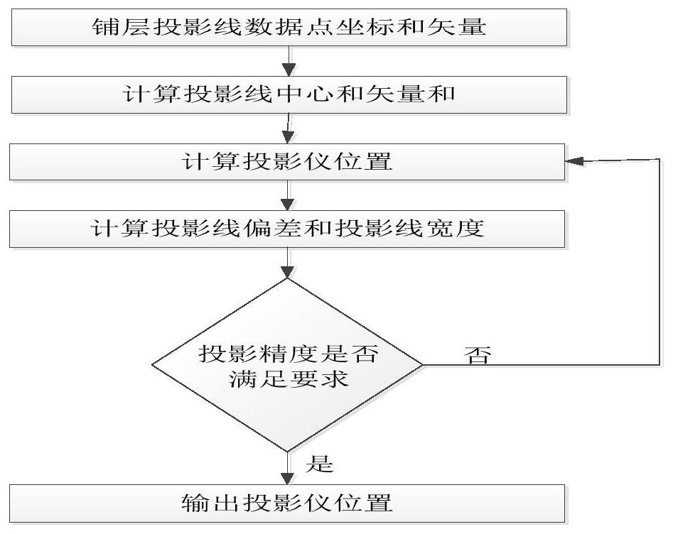
The invention belongs to the field of aviation composite material manufacturing, and in particular relates to a method for determining the position of a composite material curved surface layer laser projector. When designing a composite material layup, when the material design software of the composite material layup position line is input to the projector, it is a series of three-dimensional coordinates of the projection point and the direction of the normal vector of the projection point on the projection surface. Calculate the center point and vector sum of all projection points by analytic geometry, and then combine the projector parameters to calculate the placement position of the projector, and then comprehensively analyze the position of the projection point according to the straight angle of the projector laser and the surface deviation of the mold Deviation and projection line width. When the projection position accuracy and line width exceed the requirements, increase the number of projectors or reduce the projection area, and recalculate the projector position and projection line width. It is of great significance to improve the accuracy of composite material layup and improve the structural consistency of composite material parts.
Description
technical field [0001] The invention belongs to the field of aviation composite material manufacturing, and in particular relates to a method for calculating the layering accuracy of composite materials. [0002] technical background [0003] In the production of composite parts, the workload of laying is heavy. One of the problems is that it is difficult to accurately position the laying. In the process of manual laying, the closer the laying is, the greater the error. Manufacturing technology addresses this challenge by using a laser projection system to visualize the ply outline on the mold to enable accurate positioning of the ply. [0004] However, with the improvement of manufacturing precision requirements for composite material parts, especially when laser projection is performed on concave or convex surfaces with large curvature, the way of laser projection will have a great impact on projection accuracy, and sometimes it will be difficult to use the same projection ...
Claims
Application Information
Patent Timeline
Application Date:The date an application was filed.
Publication Date:The date a patent or application was officially published.
First Publication Date:The earliest publication date of a patent with the same application number.
Issue Date:Publication date of the patent grant document.
PCT Entry Date:The Entry date of PCT National Phase.
Estimated Expiry Date:The statutory expiry date of a patent right according to the Patent Law, and it is the longest term of protection that the patent right can achieve without the termination of the patent right due to other reasons(Term extension factor has been taken into account ).
Invalid Date:Actual expiry date is based on effective date or publication date of legal transaction data of invalid patent.
Patent Type & AuthorityPatents(China)
IPC IPC(8): B29C70/54B29C70/30B29L31/30
Inventor贾顺利修志峰高爱娟
OwnerTHE RES INST FOR SPECIAL STRUCTURES OF AERONAUTICAL COMPOSITE AVIC

