Cable storing device
A storage device and cable technology, applied in the direction of transportation and packaging, delivery of filamentous materials, thin material processing, etc., can solve problems such as instability, easily damaged joints, and difficulty in rotating the I-shaped wheel, and achieve stable transmission Effect
- Summary
- Abstract
- Description
- Claims
- Application Information
AI Technical Summary
Problems solved by technology
Method used
Image

Examples
Embodiment 1
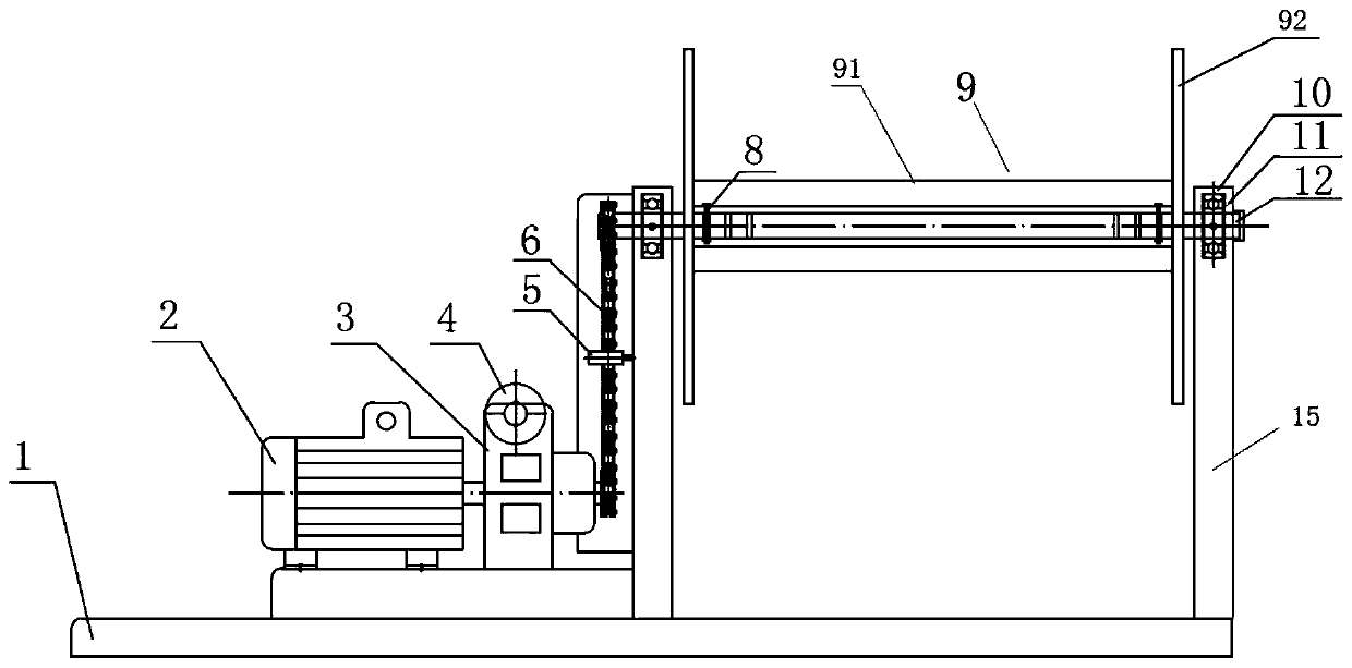
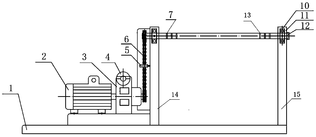
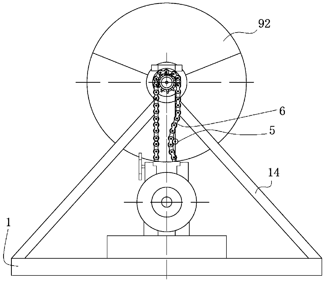
[0023] Such as Figure 1-Figure 3 As shown, the cable storage device includes a base 1. A bracket for supporting the transmission shaft 12 is arranged on the base 1. The two ends of the transmission shaft 12 are rotatably assembled on the bracket. A rope reel 9 is sheathed on the shaft 12, and the rope reel 9 is used to wind up the cables to be accommodated when the rope reel 9 rotates.
[0024] The support is divided into a left support 14 and a right support 15 arranged left and right, and the two ends of the transmission shaft 12 are assembled on the left support 14 and the right support 15 top respectively, and a room for giving way to the rotation of the rope drum 9 is formed between the left support 14 and the right support 15 . The left support 14 and the right support 15 are all spliced by channel steel, and the left support 14 and the right support 15 are triangular structures. The bracket is specifically arranged on the seat body of the base, the seat body is a f...
Embodiment 2
[0034] The difference between this embodiment and Embodiment 1 is that the driving mechanism adopts a belt transmission mechanism, and the belt transmission mechanism includes a transmission belt, a driving pulley, and a passive pulley. The driving pulley is coaxially assembled with the output shaft of the reducer, and the passive pulley It is coaxially assembled with the transmission shaft, and the transmission belt cooperates with the driving pulley and the passive pulley. The speed reducer is preferably an adjustable speed reducer.
Embodiment 3
[0036] The difference between this embodiment and Embodiment 1 is that the driving mechanism adopts a gear transmission mechanism, and the gear transmission mechanism replaces the chain transmission mechanism in Embodiment 1. The gear transmission mechanism at least includes a large gear and a pinion, the pinion is connected with the output shaft of the reducer in a coaxial transmission, and the large gear is connected with the transmission shaft in a coaxial transmission. The gearwheel meshes with the pinion for transmission. In other embodiments, an intermediate transmission gear can also be added to adjust the transmission ratio.
[0037] In this embodiment, spur gears are used for the large gear and the pinion. In other embodiments, bevel gears can also be used instead.
PUM
 Abstract
Description
Claims
Application Information
 - Generate Ideas
- Intellectual Property
- Life Sciences
- Materials
- Tech Scout
- Unparalleled Data Quality
- Higher Quality Content
- 60% Fewer Hallucinations
Browse by: Latest US Patents, China's latest patents, Technical Efficacy Thesaurus, Application Domain, Technology Topic, Popular Technical Reports.
© 2025 PatSnap. All rights reserved.Legal|Privacy policy|Modern Slavery Act Transparency Statement|Sitemap|About US| Contact US: help@patsnap.com