
Anti-collision protection guardrail of road bridge

A technology for protection fences and roads, which is applied in the direction of bridges, bridge parts, bridge construction, etc., can solve the problems of pedestrian injury, impact injury to pedestrians, inconvenient addition, etc., to avoid false touch start, reduce collision hazards, and reduce collision damage. Effect

Active Publication Date: 2019-05-21
WUHAN SURVEYING GEOTECHN RES INST OF MCC
View PDF6 Cites 3 Cited by
  • Summary
  • Abstract
  • Description
  • Claims
  • Application Information

AI Technical Summary

Problems solved by technology

The general road protection fence only considers the collision and interception of vehicles, and forms a buffer by one-time collision destruction, but does not take into account the harm caused by some road sections to pedestrians.
In some road sections, the carriageway is adjacent to the sidewalk, and the sidewalk is only raised by bricks to form a road. When leaving the lane and crashing to both sides, it is easy to hit and hurt pedestrians, especially when pedestrians are dragged and squeezed on the protective fence, causing multiple injuries to pedestrians, and it is not easy to get out of the rescue in time. Traditional guardrails cannot solve this problem
In some road sections, it is inconvenient or unnecessary to add a layer of guardrail between the sidewalk and the carriageway, but the above problems always exist

Method used


Image

  • Anti-collision protection guardrail of road bridge
  • Anti-collision protection guardrail of road bridge
  • Anti-collision protection guardrail of road bridge

Examples


Embodiment Construction

[0027] The present invention will be further described in detail below in conjunction with the accompanying drawings and specific embodiments.

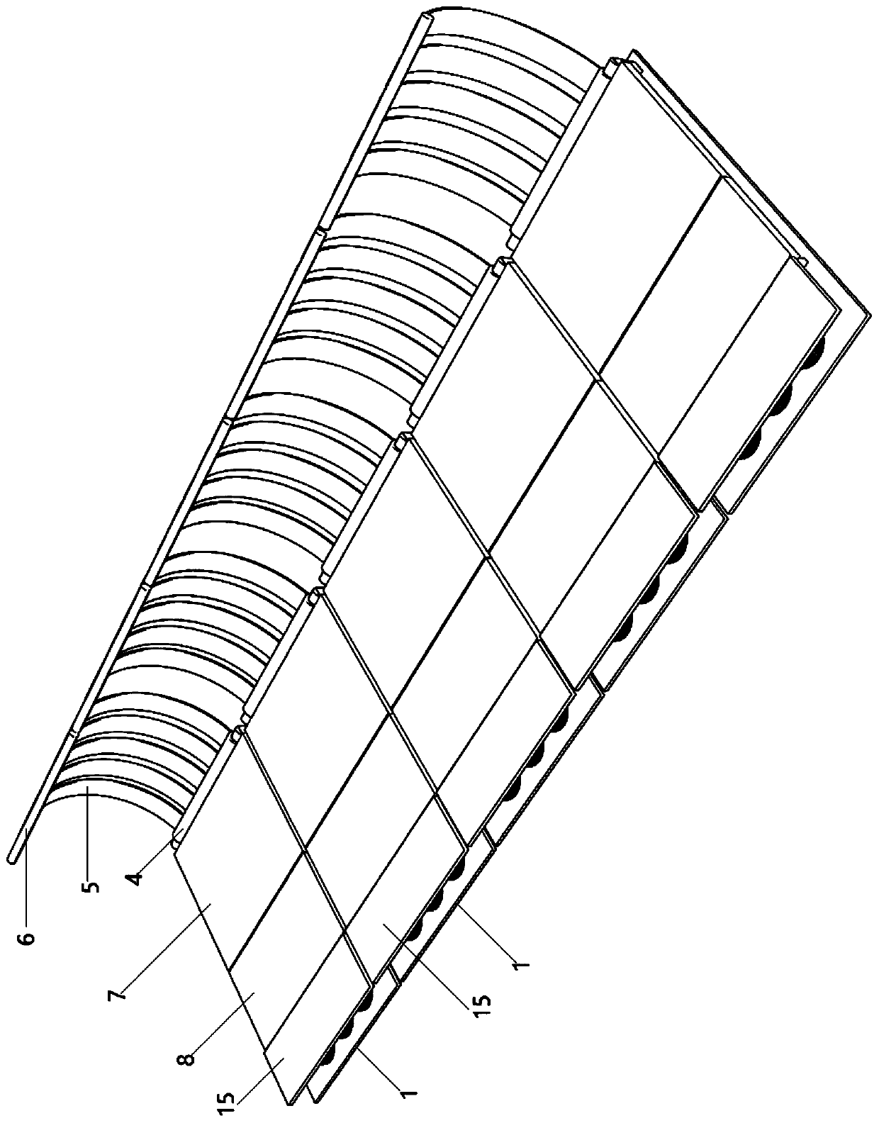
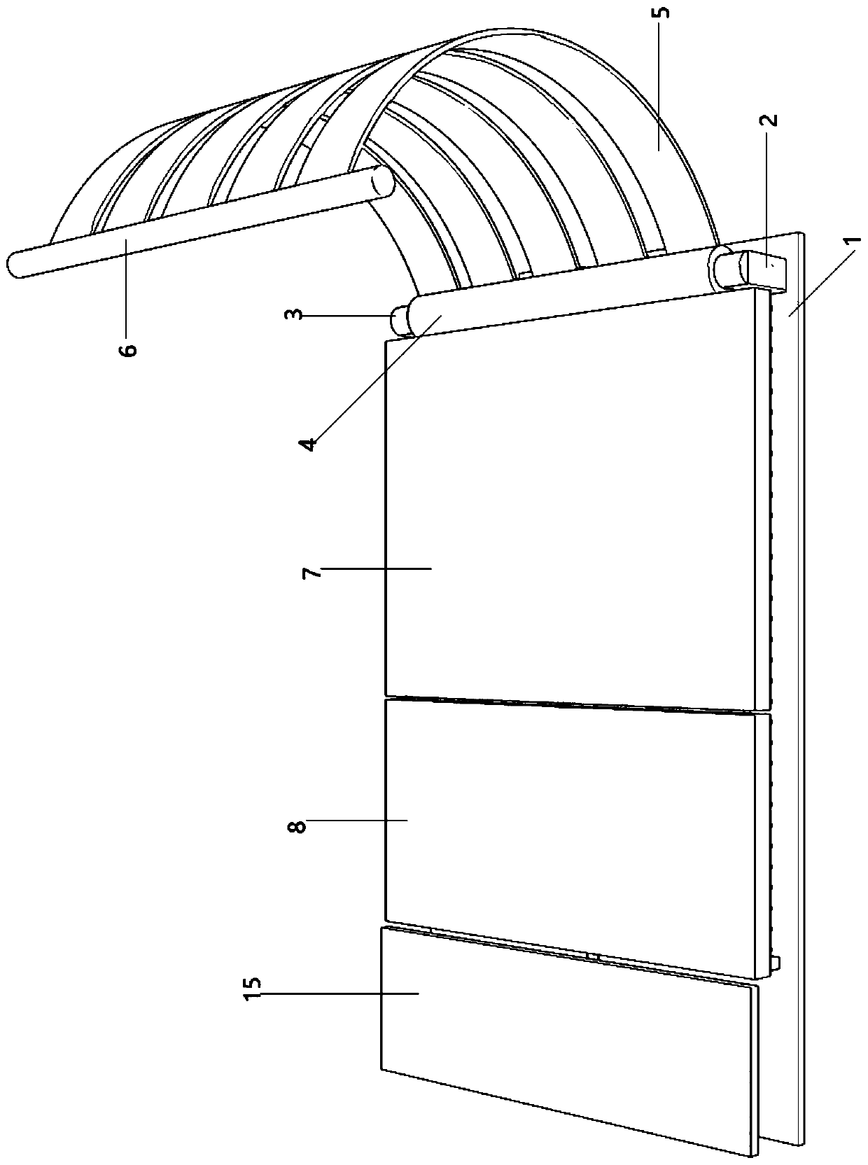
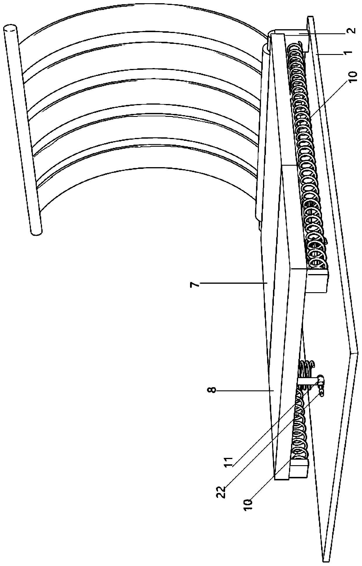
[0028] Such as Figure 1-7 As shown, the anti-collision protection fence of the road bridge includes a protection mechanism laid evenly along the road; the protection mechanism includes a base plate 1, and a protection device and a trigger device are installed on the upper end of the base plate 1; the protection device includes a main shaft 3 and a handrail 6. The front and rear sides of the right side of the bottom plate 1 are fixed with brackets 2; the front and rear sides of the main shaft 3 are fixedly connected with the front and rear sides of the brackets 2 respectively; A plurality of arc-shaped support plates 5 are evenly and fixedly connected along the front and back direction; the armrest 6 is fixedly connected with the upper end of each support plate 5; the left side of the casing 4 is fixedly connected with a horizontal ma...


PUM


Abstract

The invention discloses an anti-collision protection guardrail of a road bridge, and relates to the technical field of road guardrail devices. The guardrail comprises protection mechanisms evenly laidalong a road; each protection mechanism comprises a bottom plate, and a protection device and a trigger device are installed at the upper end of each bottom plate; each protection device comprises amain shaft and an armrest; each main shaft is rotatably sleeved with a sleeve; a horizontal main pedal is fixedly connected to the left side of each sleeve; a subsidiary pedal is rotatably connected to the left end of each main pedal through a rotating shaft; a tension spring is fixedly connected to the left end of each bracket; when springs are in a compressed state, insertion rods are located ingrooves; each trigger device comprises a support plate; guiding pipes are sleeved with starting compression springs; a support pipe is communicated with the right side of the lower portion of one guiding pipe; starting rods are slidingly connected into the support pipes; the right portions of the starting rods are in inserted connection with limiting pipes. The anti-collision protection guardrailhas the advantages that when a vehicle crashes into the roadside guardrail, the collusion damage of the vehicle is reduced, pedestrians at the inside side streets of the road are protected, and the damage to the pedestrians is reduced.

Description

technical field [0001] The invention relates to the technical field of road guardrail devices. Background technique [0002] It is often necessary to install anti-collision protection barriers on both sides of the road to prevent vehicles from rushing out of the lane through impact buffering. The general road protection fence only considers the collision and interception of vehicles, and forms a buffer by one-time collision destruction, but does not take into account the harm caused by some road sections to pedestrians. In some road sections, the carriageway is adjacent to the sidewalk, and the sidewalk only relies on bricks to form a road. When leaving the lane and crashing to both sides, it is easy to hit and hurt pedestrians, especially when pedestrians are dragged and squeezed on the protective barrier, causing multiple injuries to pedestrians, and it is difficult to achieve timely escape and rescue. Traditional guardrails cannot solve this problem. And in some road se...

Claims


Application Information

Patent Timeline
Patent Type & Authority Applications(China)
IPC IPC(8): E01D19/10
Inventor 徐海静鲍立棋徐建锐
Owner WUHAN SURVEYING GEOTECHN RES INST OF MCC
Learn More