Radio-frequency connector joint and radio-frequency connector

A radio frequency connector and electrical connection technology, which is applied in the direction of connection, two-part connection device, and parts of the connection device, can solve the problems of inaccurate antenna test results and increase the difficulty of antenna test

Pending Publication Date: 2019-05-21
GCI SCI & TECH +1
View PDF0 Cites 0 Cited by
  • Summary
  • Abstract
  • Description
  • Claims
  • Application Information

AI Technical Summary

Problems solved by technology

[0002] like figure 1 As shown, the radio frequency connector joints of the prior art generally include an inner conductor 101, an insulator 102 and an outer conductor 103, and a coaxial cable generally includes an inner conductor layer 201, an insulating layer 202 and an outer conductor layer 203, and the radio frequency connector joint and the coaxial When the cable is connected, generally the inner conductor 101 of the radio frequency connector joint is welded with the inner conductor layer 201 of the coaxial cable (the through hole 104 provided on the inner conductor 101 is filled with solder), and the outer conductor layer 201 of the coaxial cable is welded through the radio frequency connector joint. The conductor 103 is welded with the outer conductor layer 203 of the coaxial cable (filling the gap between the two with solder), but since the RF connector joint and the coaxial cable are connected by soldering, it is inevitable to cause Solder brings additional impedance, and the impedance of each soldering may be different, so when it is applied to the antenna, it increases the difficulty of antenna testing and causes antenna test results (testing the voltage standing wave ratio and phase amplitude of the antenna feed network) Inaccurate

Method used


Image

  • Radio-frequency connector joint and radio-frequency connector
  • Radio-frequency connector joint and radio-frequency connector
  • Radio-frequency connector joint and radio-frequency connector

Examples


Embodiment Construction

[0027] The specific implementation manners of the present invention will be further described in detail below in conjunction with the accompanying drawings and embodiments. The following examples are used to illustrate the present invention, but are not intended to limit the scope of the present invention.

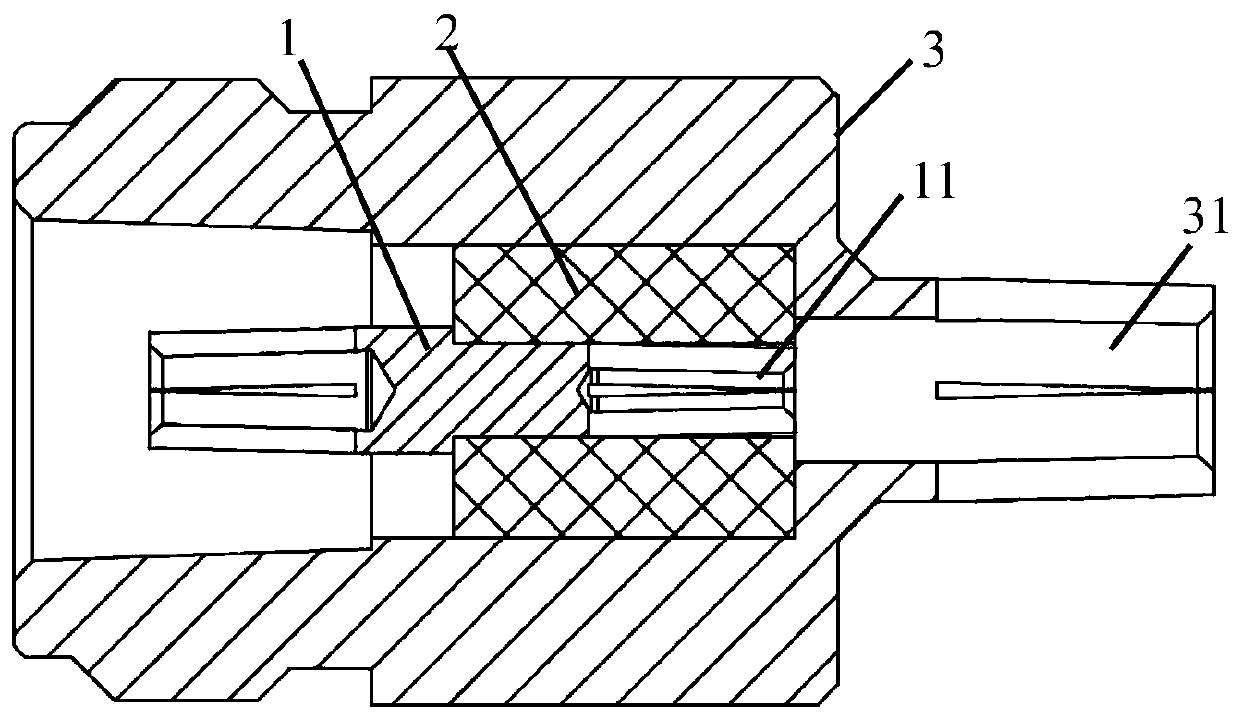
[0028] In the description of the present invention, directions such as up, down, left, right, front and back, and descriptions of top and bottom are all for figure 2 As a limitation, when the placement method of the radio frequency connector joint changes, its corresponding orientation and the description of the top and bottom will also change according to the change of the placement method, and the present invention will not repeat them here.

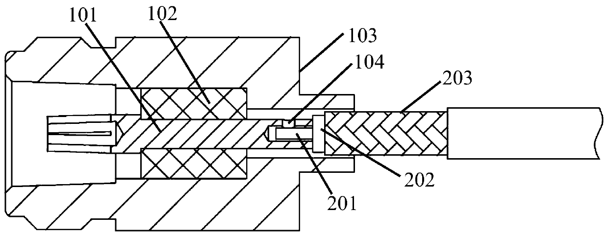
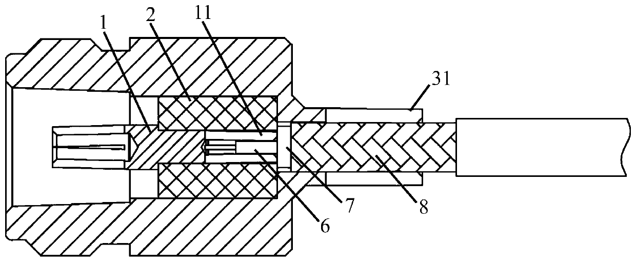
[0029] combine Figure 2 to Figure 4 As shown, the embodiment of the present invention provides a radio frequency connector, which includes a radio frequency connector joint, the radio frequency connector joint includes an inner ...


PUM


Abstract

The invention relates to the technical field of communication, and discloses a radio-frequency connector joint and a radio-frequency connector. The radio-frequency connector joint comprises an inner conductor, an insulator and an outer conductor; the insulator is clamped on the outer conductor, and the inner conductor is connected to the insulator, so that the inner conductor is fixed; a first inserting part is arranged at the right end of the inner conductor; a second inserting part is arranged at the right end of the outer conductor; the first inserting part and the second inserting part arecoaxial; when the radio-frequency connector joint and a coaxial cable are installed, a user can quickly insert an inner conductor layer and an outer conductor layer of the coaxial cable into the first inserting part and the second inserting part to insert the coaxial cable into the radio-frequency connector joint, so that the coaxial cable can be firmly connected to the radio-frequency connectorjoint; and the connecting position is enabled to be the same during each installation to ensure that the impedance is kept consistent when the radio-frequency connector joint and the coaxial cable areinstalled each time, so that the accuracy of antenna testing is improved.

Description

technical field [0001] The invention relates to the technical field of communication, in particular to a radio frequency connector joint and a radio frequency connector. Background technique [0002] Such as figure 1 As shown, the radio frequency connector joints of the prior art generally include an inner conductor 101, an insulator 102 and an outer conductor 103, and a coaxial cable generally includes an inner conductor layer 201, an insulating layer 202 and an outer conductor layer 203, and the radio frequency connector joint and the coaxial When the cable is connected, generally the inner conductor 101 of the radio frequency connector joint is welded with the inner conductor layer 201 of the coaxial cable (the through hole 104 provided on the inner conductor 101 is filled with solder), and the outer conductor layer 201 of the coaxial cable is welded through the radio frequency connector joint. The conductor 103 is welded with the outer conductor layer 203 of the coaxial...

Claims


Application Information

Patent Timeline
IPC IPC(8): H01R13/02H01R13/40H01R13/516H01R24/44
Inventor 陈韶明邹光健潘蓉
Owner GCI SCI & TECH
Why Eureka
Try Eureka