Windscreen wiper and vehicle with windscreen wiper

A windshield and wiper technology, which is applied in vehicle maintenance, vehicle cleaning, transportation and packaging, etc., can solve problems such as unfavorable spray angles and achieve the effect of preventing damage.

Inactive Publication Date: 2019-05-21
A RAYMOND & CO
View PDF5 Cites 2 Cited by
  • Summary
  • Abstract
  • Description
  • Claims
  • Application Information

AI Technical Summary

Problems solved by technology

This always results in unfavorable angular orientations with respect to the spray angle for structures with bottom hood cleaning nozzles

Method used


Image

  • Windscreen wiper and vehicle with windscreen wiper
  • Windscreen wiper and vehicle with windscreen wiper
  • Windscreen wiper and vehicle with windscreen wiper

Examples


Embodiment Construction

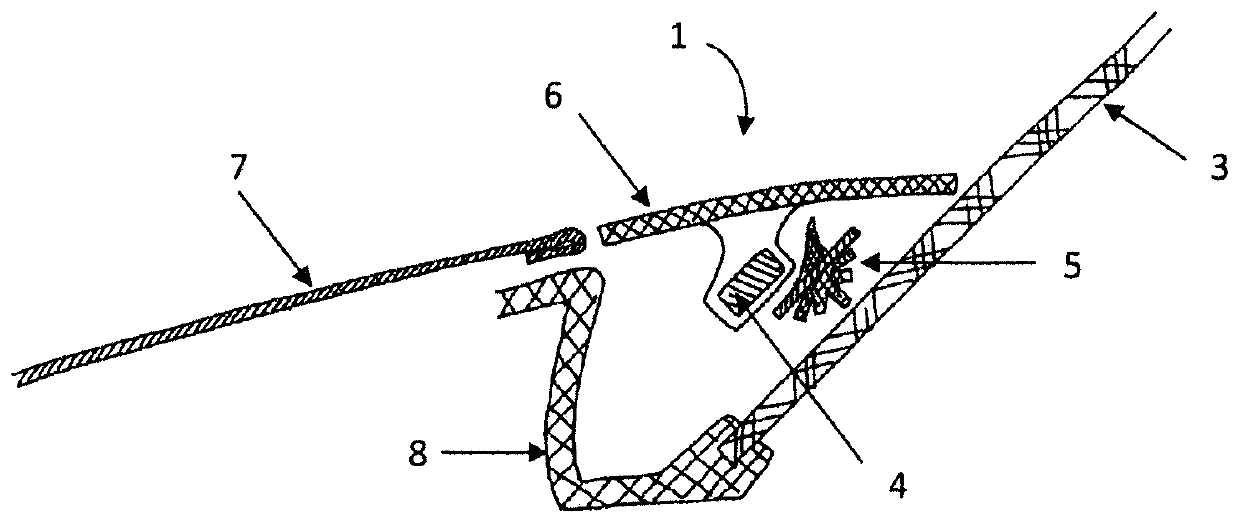
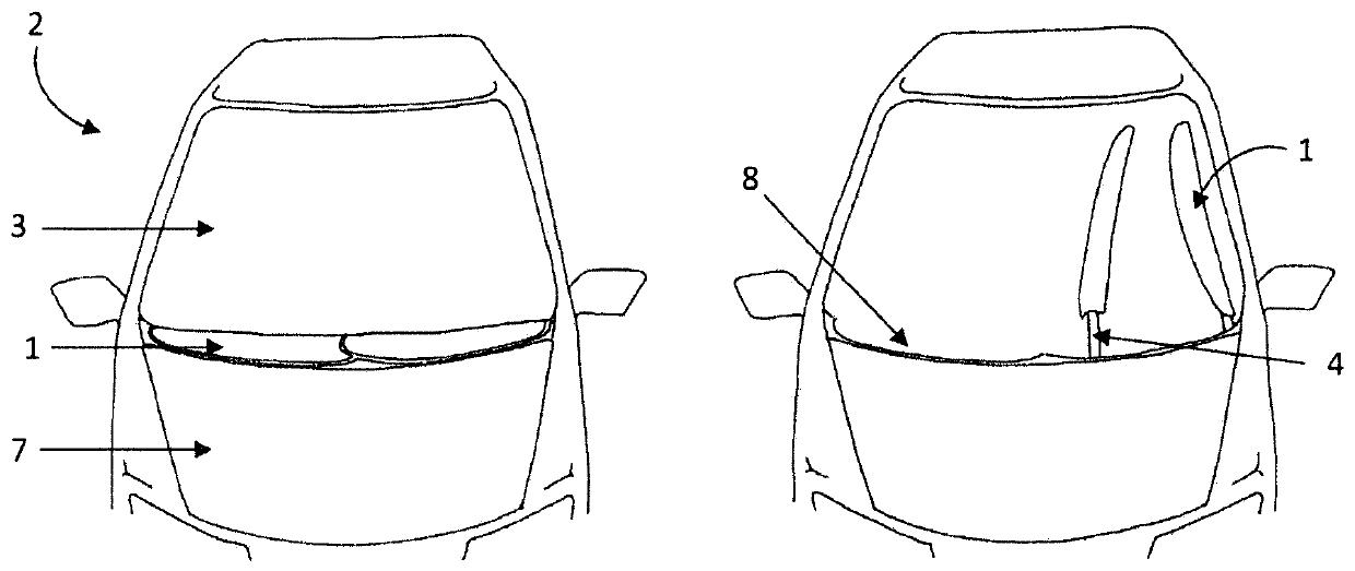
[0073] exist figure 1 shows a sectional view through the front area of ​​a vehicle 2 with a front cowl 7 made of metal or plastic, a windscreen wiper 1 according to the invention in a cavity 8 and a windshield glass3. Here, the front cover 7 is preferably flush with the recess 8 . In particular, the two components can be fastened to one another in a clamped or locked manner. On the side opposite the front hood 7 , the cavity 8 is firmly connected to another component of the vehicle 2 , in particular to the frame of the windshield 3 or to the windshield 3 itself. The connection is preferably glued here, wherein locking or clamping likewise represent possible realizations. The recess 8 or gap between the windshield 3 and the front cowl 7 is at least substantially covered and filled here by the windshield wiper 1 . The cover 6 of the windshield wiper 1 is preferably flush with the two outer edges of the cavity 8 so that a mainly smooth transition from the front cowl 7 to the ...


PUM


Abstract

The invention relates to a windscreen wiper with a wiper arm and a wiper blade, and a cover attached to the wiper arm, into which at least one nozzle for windscreen washer fluid is built. The supply system for the windscreen washer fluid can also be built into the cover. Furthermore, the cover is designed such that the wiper blade, the wiper arm and the cover can be detached from each other. The cover closes the gap between the bonnet and the windscreen in the idle state and can be made compact for the operating state by means of a mechanism.

Description

technical field [0001] The invention relates to a windshield wiper, a vehicle with a front hood, a windshield and a windshield wiper as well as the use of such a windshield wiper and the possibility of using such a windshield wiper method of implementation. Background technique [0002] A housing for covering a rear window wiper of a motor vehicle is known from DE 29708554 U1. The stationary housing part is molded cavity-like into the rear cover. The cover is fixedly connected to the wiper arm and is substantially flush with the housing opening in the rest position of the wiper arm. If the rear window wiper is put into operation, it must first be moved linearly along the drive shaft of the windscreen wiper in order to leave the housing cavity. Here, it is important to protect the wiper blades from dirt and air resistance. [0003] In today's vehicles, the motor housing is moving closer and closer to the windshield. This has both aerodynamic reasons and pedestrian protec...

Claims


Application Information

Patent Timeline
Patent Type & Authority Applications(China)
IPC IPC(8): B60S1/04B60S1/32B60S1/52
CPCB60S1/0402B60S1/0463B60S1/32B60S1/522B60S1/0405
Inventor J·吉玛K·博德
Owner A RAYMOND & CO
Why Eureka
Try Eureka