
Core for current transformer

A technology of current transformers and magnetic cores, which is applied in the manufacture of transformer/inductor cores, inductors, inductors/transformers/magnets, etc., can solve the problem of reducing the power acquisition efficiency of traditional magnetic cores, reducing power acquisition efficiency, and reducing magnetic permeability Ratio and other issues, to achieve the effect of improving power acquisition efficiency, increasing size, and increasing magnetic permeability

Active Publication Date: 2019-05-21
AMOSENSE
View PDF9 Cites 0 Cited by
  • Summary
  • Abstract
  • Description
  • Claims
  • Application Information

AI Technical Summary

Problems solved by technology

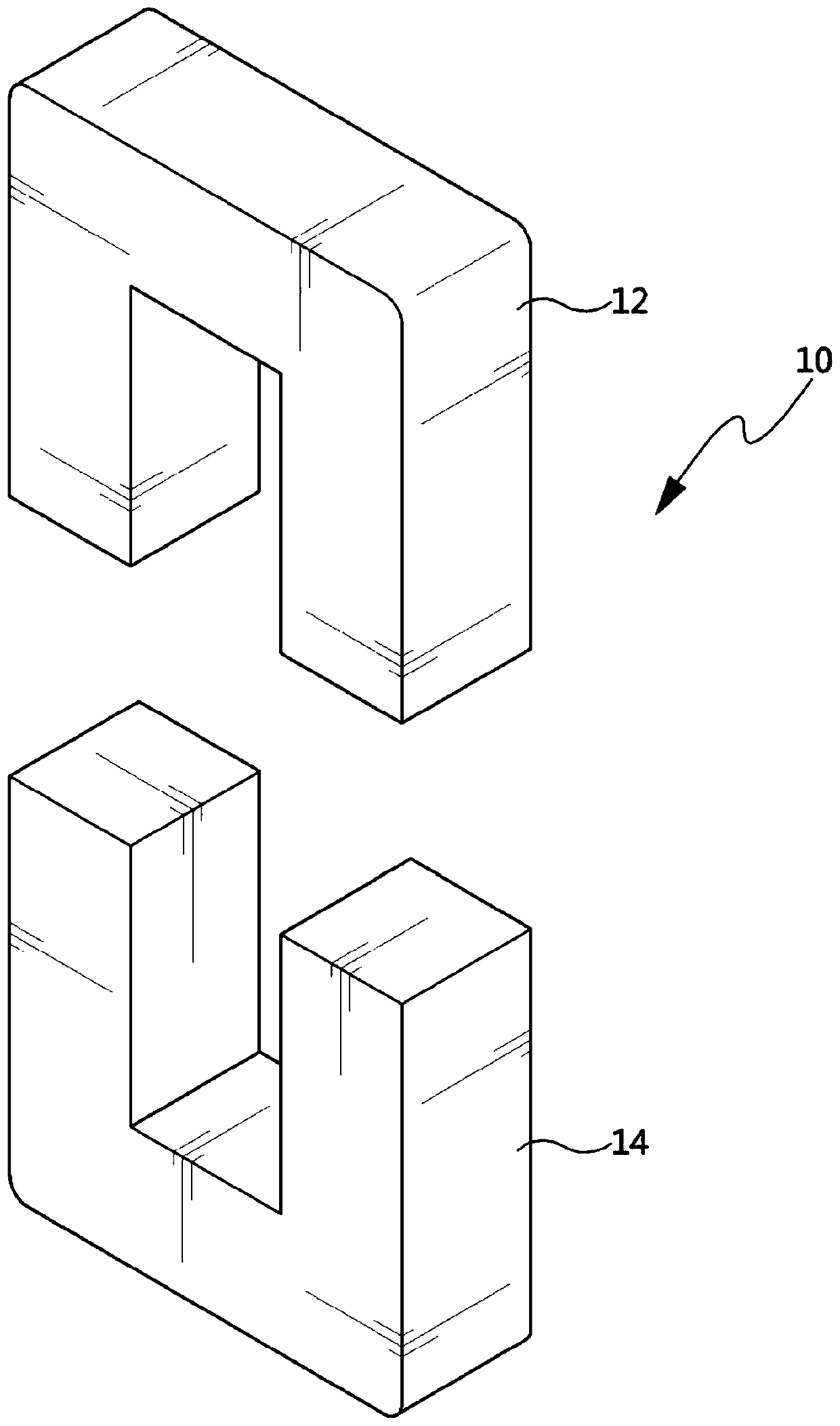
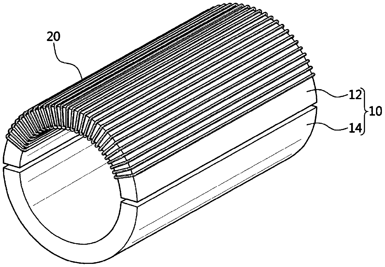
At this time, there is a problem in that since the upper magnetic core 12 and the lower magnetic core 14 are formed with a bent portion having an angle of about 90 degrees, a stress region on the magnetic path is generated to lower the magnetic permeability.
[0006] In addition, the conventional magnetic core used for the current transformer 10 has a problem in that the inductance decreases due to the reduction of the magnetic permeability, thereby reducing the power acquisition efficiency when the conventional magnetic core is mounted on the current transformer.
[0008] In addition, the conventional magnetic core used for the current transformer 10 has a problem in that power acquisition efficiency is lowered when the conventional magnetic core is mounted on the current transformer due to a reduction in inductance.

Method used


Image

  • Core for current transformer
  • Core for current transformer
  • Core for current transformer

Examples


Embodiment Construction

[0033] Hereinafter, the most preferred embodiments of the present disclosure will be described with reference to the accompanying drawings so that those skilled in the art to which the present disclosure pertains can easily practice the technical spirit of the present disclosure. First, when adding reference numerals to components in each drawing, it should be noted that the same components are denoted by the same reference numerals even if they are shown in different drawings. Also, in the following description of the present disclosure, when it is determined to obscure the subject matter of the present disclosure, a detailed description of related known configurations or functions will be omitted.

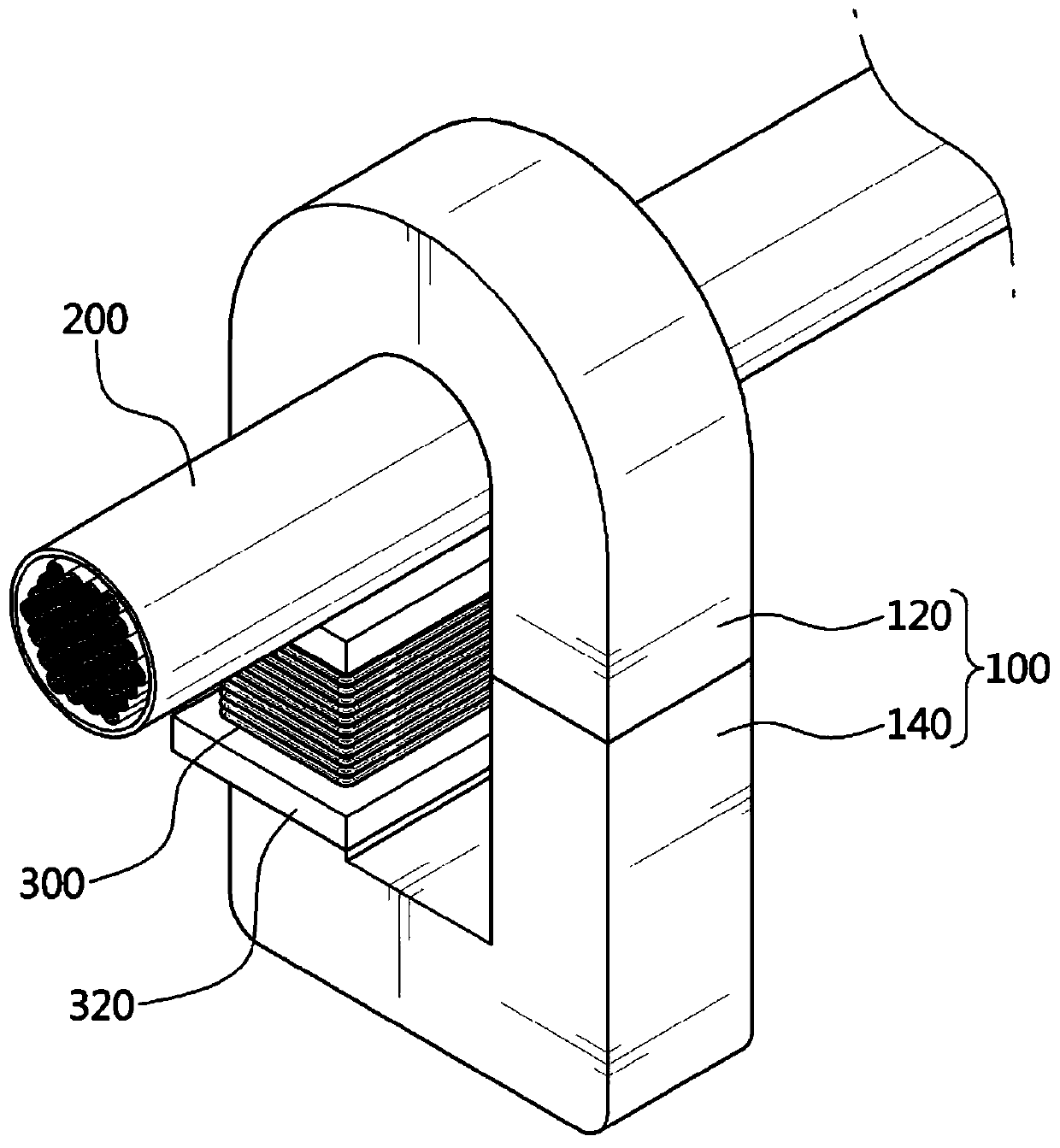
[0034] refer to image 3 , the magnetic core for the current transformer 100 is configured to include an upper magnetic core 120 and a lower magnetic core 140 in which the power line 200 is accommodated, and a skeleton 300 is installed in the lower magnetic core 140, and the skel...


PUM


Abstract

The invention discloses a core for a current transformer having an upper core formed in a round shape in which the both ends of the upper core are disposed at a position lower than the center of a received power line, thereby minimizing the stress of a magnetic path and increasing magnetic permeability to improve magnetic induction efficiency. The suggested core for a current transformer comprises: an upper core which is bent in a semicircular shape to form a receiving groove and has both ends extending in the downward direction and arranged to be spaced apart from each other; and a lower corewhich is disposed at a lower portion of the upper core and has both ends extending in the upper direction and arranged to face the both ends of the upper core.

Description

technical field [0001] The present disclosure relates to a magnetic core for a current transformer, and more particularly, to a magnetic core mounted on a current transformer installed in a transmission line or a distribution line for using the phenomenon of magnetic induction Source power and sense current. Background technique [0002] Recently, as interest in power supply methods using the magnetic induction phenomenon has increased, various types of magnetic induction power supply devices have been developed. [0003] The magnetic induction type power supply device includes a current transformer installed in a power line through which a large-capacity current flows, such as a transmission line, a distribution line, and the like. A magnetic induction type power supply device converts electric power obtained by a magnetic induction phenomenon in a current transformer into DC to supply the DC to a load. [0004] At this time, the current transformer is configured to inclu...

Claims


Application Information

Patent Timeline
Patent Type & Authority Applications(China)
IPC IPC(8): H01F38/28H01F38/30H01F41/02
CPCH01F3/10H01F38/30H01F38/28H01F41/02H01F27/24H01F41/0246
Inventor 韩澈承罗元蒜朴晋杓金荣俊高在俊
Owner AMOSENSE
Learn More