Double-shaft fluxgate current sensor

A technology of current sensor and current transformer, which is applied in the direction of voltage/current isolation, measuring current/voltage, instruments, etc., can solve the problems of long response time, low sensitivity, weak signal, etc., and achieve the suppression of the influence of measurement work and wear resistance Excellent performance and corrosion resistance, and the effect of suppressing input signal noise

Inactive Publication Date: 2012-04-04
HEBEI UNIV OF TECH
View PDF8 Cites 63 Cited by
  • Summary
  • Abstract
  • Description
  • Claims
  • Application Information

AI Technical Summary

Problems solved by technology

The disadvantages of the device are: (1) the device adopts a rod-shaped magnetic core, and the output signal of the single-rod fluxgate sensor contains a large fundamental wave component that has nothing to do with the environmental magnetic field information, which needs to be removed by the sensor signal processing circuit Part; (2) The device uses two active components, adding an additional drive circuit, resulting in a complex structure and increased cost; (3) The device uses an open-loop sensor, and the magnetic loss in the magnetic circuit causes a long response time and insufficient bandwidth, relatively large temperature-related gain drift, and low sensit

Method used


Image

  • Double-shaft fluxgate current sensor
  • Double-shaft fluxgate current sensor
  • Double-shaft fluxgate current sensor

Examples


Embodiment 1

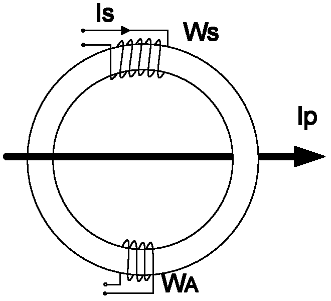
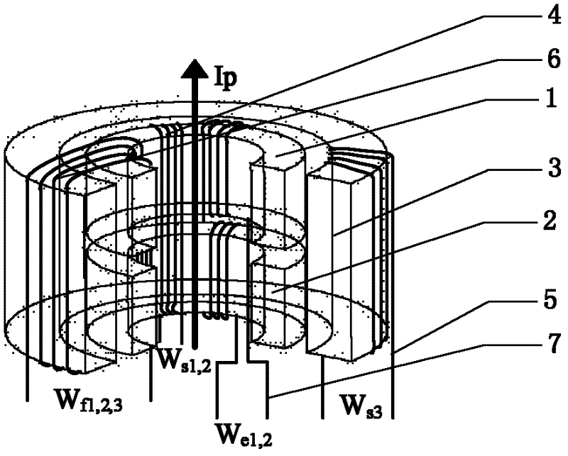
[0058] as above figure 2 The embodiment shown in the device is a fluxgate detection probe of a biaxial fluxgate current sensor and a zero-flux current transformer, wherein the fluxgate detection probe is composed of an inner annular magnetic core a1 and an inner annular magnetic core b2 arranged side by side , excitation winding W e1,2 7 is a wire wound on the inner ring magnetic core a1 for 100 turns to form the excitation winding W e1,2 7W e1 part, and then wind 100 turns on the inner ring core b2 in the opposite direction to form the excitation winding W e1,2 7W e2 part, the induction winding W s1,2 4 Wind the two inner ring cores a1 and b2 placed side by side together for 70 turns, in which the induction winding W on the inner ring core a1 s1,2 4 parts called W s1 , the induction winding W on the inner ring core b2 s1,2 4 parts called W s2 ; The zero-flux current transformer consists of an outer ring core 3 and a secondary side winding W S3 5 composition, the se...

Embodiment 2

[0062] In addition to excitation winding W e1,2 7 is a wire wound on the inner ring magnetic core a1 for 100 turns to form the excitation winding W e1, 2 7W e1 part, and then wind 100 turns on the inner ring core b2 in the opposite direction to form the excitation winding W e1,2 7W e2 part, the induction winding W s1,2 4 Wind the two inner ring cores a1 and b2 placed side by side together for 70 turns, in which the induction winding W on the inner ring core a1 s1,2 4 parts called W s1 , the induction winding W on the inner ring core b2 s1,2 4 parts called W s2 Except, other is with embodiment 1.

[0063] The above-mentioned biaxial fluxgate current sensor is used for the measurement experiment of low-frequency alternating current. The measurement method and process are the same as in Embodiment 1. The measured current is from -30A to 30A, and the voltage on the sampling resistor 17 is measured.

Embodiment 3

[0065] In addition to excitation winding W e1,2 7 is a wire wound on the inner ring magnetic core a1 for 100 turns to form the excitation winding W e1, 2 7W e1 part, and then wind 100 turns on the inner ring core b2 in the opposite direction to form the excitation winding W e1,2 7W e2 part, the induction winding W s1,2 4 Wind the two inner ring cores a1 and b2 placed side by side together for 70 turns, in which the induction winding W on the inner ring core a1 s1,2 4 parts called W s1 , the induction winding W on the inner ring core b2 s1,2 4 parts called W s2 Except, other is with embodiment 1.

[0066] The above-mentioned biaxial fluxgate current sensor is used for the measurement experiment of high-frequency alternating current. The measurement method and process are the same as those in Embodiment 1. The frequency of the measured current can reach up to 20KHz, and the voltage on the sampling resistor 17 is measured.


PUM

PropertyMeasurementUnit
Saturation flux densityaaaaaaaaaa
Diameteraaaaaaaaaa

Abstract

The invention discloses a double-shaft fluxgate current sensor of the invention, relating to a device for measuring the current, comprising a fluxgate detecting probe, a zero flux current transformer and a signal processing circuit, wherein the fluxgate detecting probe is composed of two inner annular magnetic cores a and b, an excitation winding and an induction winding, wherein the fluxgate detecting probe is composed of an outer annular magnetic core and a secondary side winding; two inner annular magnetic cores a and b and the outer annular magnetic core are wound via a feedback winding; the signal processing circuit includes an exciting circuit and a detecting circuit, wherein the exciting circuit includes an exciting signal generating circuit, a voltage comparer and a power amplifying circuit; the detecting circuit includes an RLC resonant circuit, a differential amplifier circuit, a bandpass filtering circuit, a phase sensitive detecting circuit, a differential smooth filteringcircuit, a feedback circuit, a voltage controlled current source and a sampling resistor. The invention eliminates the measurement error of the current fluxgate current sensor by means of a closed loop formed by the feedback winding.

Description

technical field [0001] The technical solution of the invention relates to a device for measuring current, in particular to a dual-axis fluxgate current sensor. Background technique [0002] With the development of power electronics technology, the application range of high-precision current sensors is more extensive. Especially the non-contact current sensor has broad development prospects in industrial applications. Non-contact current measurement can ensure the personal safety of the measuring staff and the stable operation of the system. Current measurement methods mainly include: voltage divider resistors, current transformers, Hall current sensors, Rogowski coils (Rogowski coils), fluxgate current sensors and magneto-impedance effect magnetic sensors. Among them, the Hall current sensor and the fluxgate current sensor can detect AC and DC. The Hall current sensor can detect thousands of amperes of current, and the accuracy range is between 0.5% and 2%. However, the d...

Claims


Application Information

Patent Timeline
IPC IPC(8): G01R19/00G01R15/00G01R15/18
Inventor 杨晓光汪友华谢存福张波刘航
Owner HEBEI UNIV OF TECH
Why Eureka
Try Eureka