
Branch circuit monitor power measurement

Active Publication Date: 2010-09-16
SCHNEIDER ELECTRIC USA INC
View PDF110 Cites 56 Cited by
  • Summary
  • Abstract
  • Description
  • Claims
  • Application Information

AI Technical Summary

Problems solved by technology

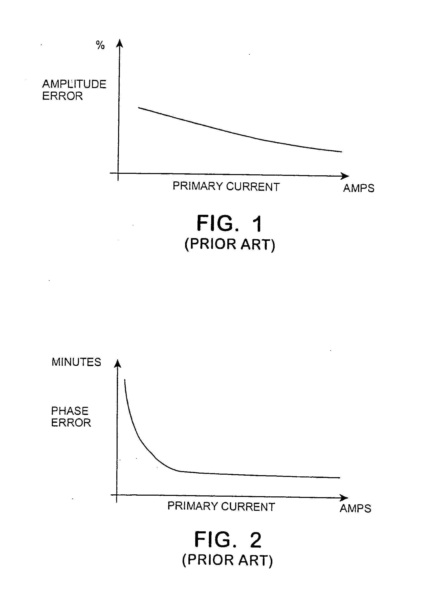
However, actual transformers are not ideal transformers and the magnetization of the core of the current transformer produces errors that reduce the accuracy of the readings produced by the meter.
While temporally offsetting the current and voltage sampling to accommodate phase error significantly reduces the data processing requirements of the meter, the differential between the current sampling and the voltage sampling can make it difficult to sample at a sufficiently high frequency to accommodate the large number of current sensors that characterize a branch circuit monitor and can interfere with obtaining a sufficient number of current samples from each of the sensors during each AC cycle to adequately describe the current waveform to avoid aliasing.
In addition, due to the large number of current sensors that characterize a branch circuit monitor, capturing a voltage sample corresponding to each of the current samples produces a substantial number of voltage samples increasing the bandwidth and the cost of the data processing unit of the meter.

Method used


Image

  • Branch circuit monitor power measurement
  • Branch circuit monitor power measurement
  • Branch circuit monitor power measurement

Examples


Embodiment Construction

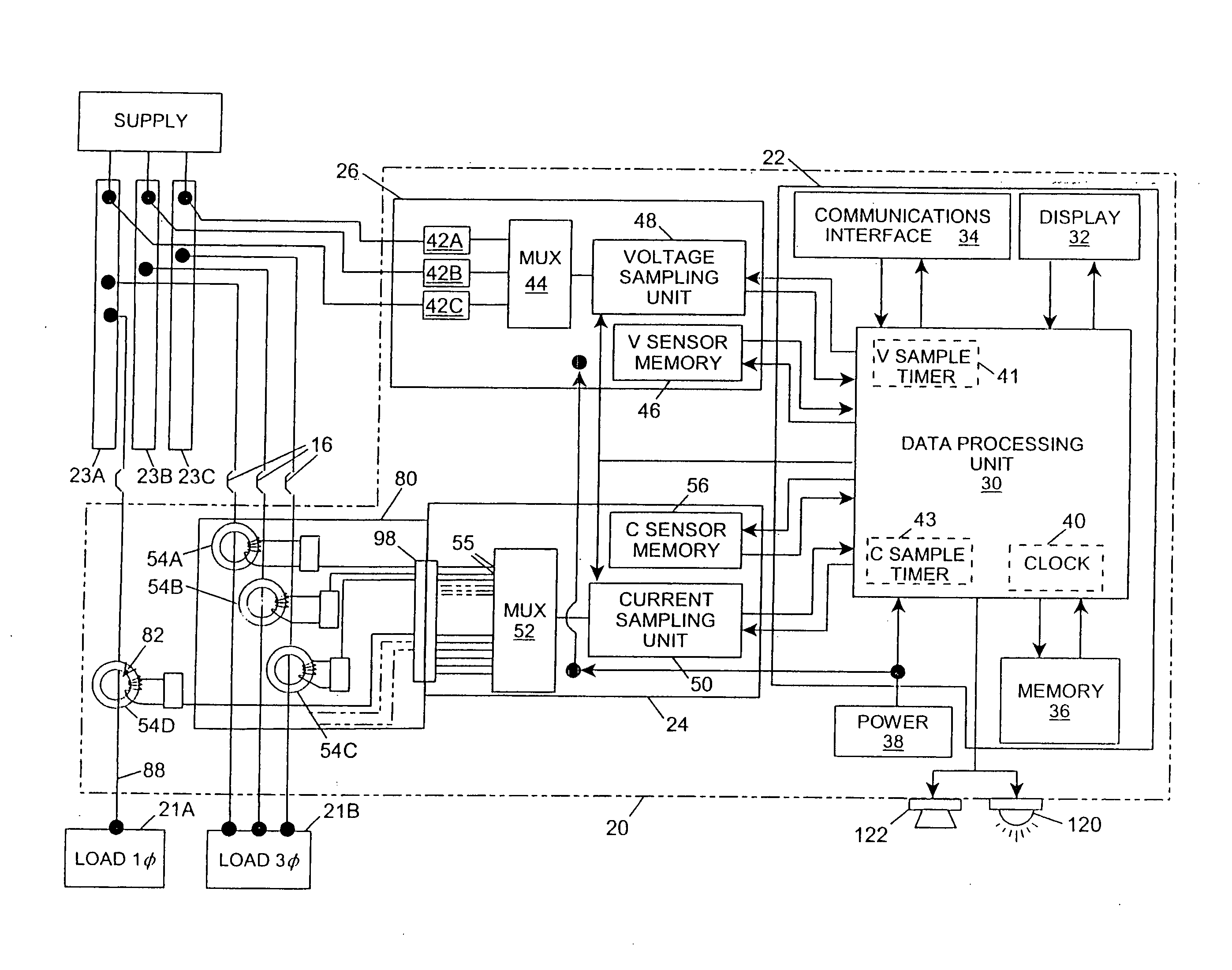
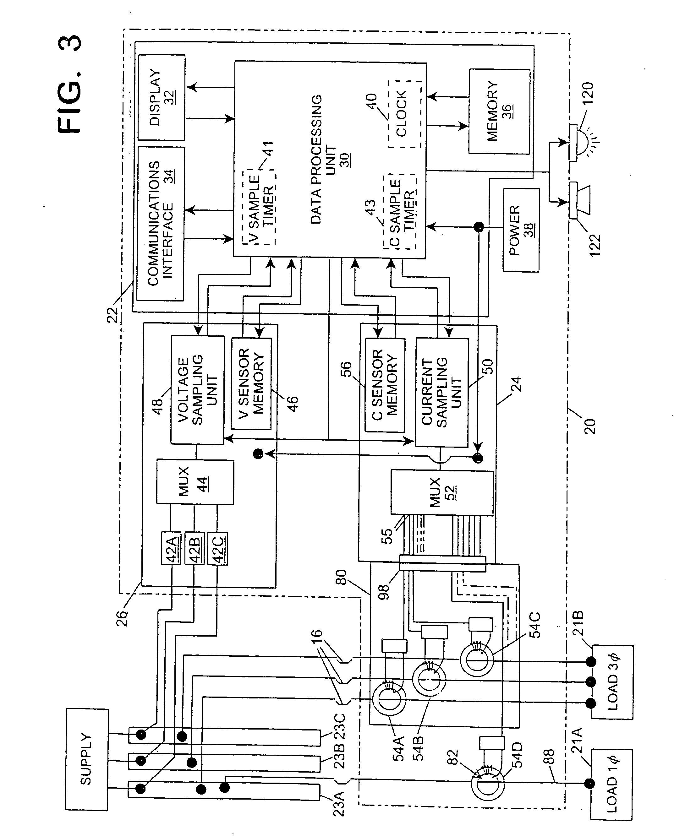
[0030]Referring in detail to the drawings where similar parts are identified by like reference numerals, and, more particularly to FIG. 3, a branch circuit monitor 20 arranged to monitor the voltage and current in a plurality of branch circuits comprises, generally, a data processing module 22, a current module 24 and a voltage module 26. The data processing module 22 comprises a data processing unit 30 which, typically, comprises at least one microprocessor or digital signal processor (DSP). The data processing unit 30 reads and stores data received periodically from the voltage module and the current module, and uses that data to calculate the current, voltage, power and other electrical parameters that are the meter's output. The calculated values may be output to a display 32 for viewing at the meter or output to a communications interface 34 for transmission to another data processing system, such as a building management computer, for remote display or use in automating or man...


PUM


Abstract

In a digital branch circuit monitor, compensation for the phase error is accomplished by selecting a voltage sampled at a time temporally offset from the sampling time of the current by an interval quantifying the phase shift of the secondary current relative to the primary current that is characteristic of a current transformer.

Description

CROSS-REFERENCE TO RELATED APPLICATIONS[0001]This application claims the benefit of Provisional App. No. 61 / 210,119, filed Mar. 13, 2009.BACKGROUND OF THE INVENTION[0002]The present invention relates to a branch circuit monitor and, more particularly, to a method of compensating for phase error when making a power measurement with a branch circuit monitor.[0003]The total power consumption of a building or other facility is monitored by the electric utility with a power meter located between the utility's distribution transformer and the facility's power distribution panel. However, in many instances it is desirable to sub-meter or attribute the facility's power usage and cost to different occupancies, buildings, departments, or cost centers within the facility or to monitor the power consumption of individual loads or groups of loads, such as motors, lighting, heating units, cooling units, machinery, etc. These single phase or multi-phase electrical loads are typically connected to ...

Claims


Application Information

Patent Timeline
IPC IPC(8): G01R19/00G01R13/00
CPCG01R21/133G01R21/06
Inventor MCCREA, BENJAMIN J.RUPERT, MATTHEWBITSCH, MICHAEL
Owner SCHNEIDER ELECTRIC USA INC
Learn More