Opening current transformer capable of being installed in powered-on mode

A technology for current transformers and shells, which is applied in the field of open current transformers, which can solve the problems of difficult compliance with partial discharge indicators, weak insulation at openings, and reduced wire holding strength, so as to avoid the problem of weak insulation, low cost, and strengthen the holding The effect of line strength

Active Publication Date: 2016-02-24
ELECTRIC POWER RES INST OF GUANGDONG POWER GRID
View PDF8 Cites 58 Cited by
  • Summary
  • Abstract
  • Description
  • Claims
  • Application Information

AI Technical Summary

Problems solved by technology

The disadvantage of this structure is: if live installation is required, auxiliary tooling and procedures are required, and the installation is complicated. Usually, the operator needs to wear professional high-voltage work clothes and stand on a live work vehicle to complete the installation; in addition, high Low voltage needs reliable insulation, but due to the weak insulation at the opening, the partial discharge index is difficult to meet the industry's "national standard", so there is a big safety hazard
However, due to the common use of spring press...

Method used


Image

  • Opening current transformer capable of being installed in powered-on mode
  • Opening current transformer capable of being installed in powered-on mode
  • Opening current transformer capable of being installed in powered-on mode

Examples


Embodiment Construction

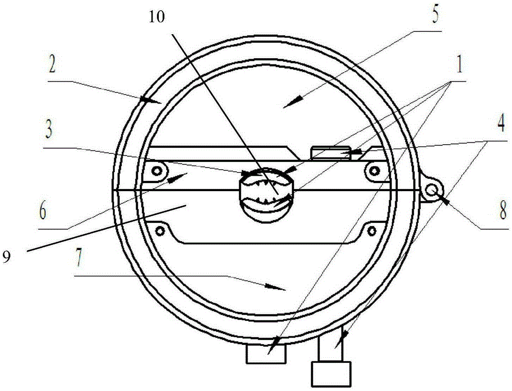
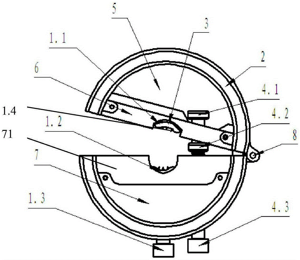
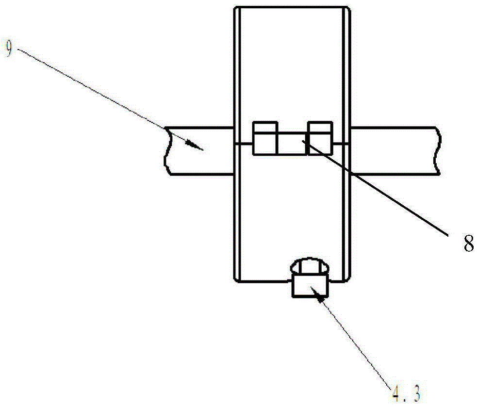
[0029] Such as Figure 1~6 As shown, it is an open current transformer that can be installed with electricity in the present invention, including a short cylindrical shell and a coil. In this embodiment, the coil is a complete circular flexible coil, specifically the flexible Rogowski coil 2, the flexible Rogowski coil 2 The coil 2 is a hollow coil that can be bent arbitrarily. It is embedded in the full circular shell formed by the moving half-ring shell 5 and the static half-ring shell 7 along the circumference, forming a secondary winding that is used as a primary winding relative to the primary busbar. . The side wall of the casing is a double-layer structure to form an annular cavity for containing the coil, and the casing is divided into two butt-joint semi-cylindrical bodies as the dynamic half-ring shell 5 and the static half-ring shell 7, and the moving half-ring shell 5 and the static half-ring shell The housing 7 is hingedly connected at one of the butt joints, and...


PUM


Abstract

The invention discloses an opening current transformer capable of being installed in a powered-on mode. A shell is divided into two oppositely-connected half cylinders used as a movable semicircular shell body and a fixed semicircular shell body. The two shell bodies are hinged at one oppositely-connected position. A longitudinally-extending movable beam is arranged at an opening of the movable semicircular shell body. A longitudinally-extending fixed beam is arranged at an opening of the fixed semicircular shell body. The fixed beam and the movable beam are blocky bodies and make contact with each other when the two shell bodies are oppositely connected. The contact face of the movable beam and the contact face of the fixed beam are each provided with a longitudinally-extending notch. An upper piercing wire card is arranged in the notch of the movable beam. A lower piercing wire card is arranged in the notch of the fixed beam. The upper piercing wire card and the lower piercing wire card are oppositely connected to form a wire holding hole. The upper piercing wire card and the lower piercing wire card are each provided with metal teeth piercing a bus metal core. The opening current transformer further comprises an opening and closing mechanism making the upper piercing wire card and the lower piercing wire card opened or closed. The opening current transformer is reliable in insulation, capable of being firmly installed on a bus, and capable of being widely applied to occasions for measuring primary current and temperature of the bus.

Description

technical field [0001] The invention relates to a current transformer, in particular to an open current transformer capable of live installation. Background technique [0002] Because the open or open current transformer can be installed without disconnecting the high-voltage primary bus, which brings great convenience to users, so this current transformer has been widely used in recent years. Judging from the currently applied product forms, open current transformers mainly have the following two structural forms: [0003] The first structure adopts the general high-voltage transformer structure. This structure is to isolate the primary and secondary windings through insulation, and complete the measurement and calculation of the primary current on the secondary side. The disadvantage of this structure is: if live installation is required, auxiliary tooling and procedures are required, and the installation is complicated. Usually, the operator needs to wear professional hi...

Claims


Application Information

Patent Timeline
IPC IPC(8): H01F38/30H01F27/02H01F41/00
Inventor 林国营张永旺陈喆赵伟潘峰
Owner ELECTRIC POWER RES INST OF GUANGDONG POWER GRID
Why Eureka
Try Eureka