Collision energy-absorbing device and front anti-collision beam assembly

A technology of collision energy absorption and front anti-collision beams, which is applied to bumpers and other directions, can solve problems such as the collapse route and direction impact of energy-absorbing boxes, and achieve the effects of improving collision safety, good protection, and increasing buffer time

Inactive Publication Date: 2019-05-24
SHAANXI TONGJIA AUTOMOBILE
View PDF4 Cites 0 Cited by
  • Summary
  • Abstract
  • Description
  • Claims
  • Application Information

AI Technical Summary

Problems solved by technology

[0005] The purpose of the present invention is to provide a collision energy-absorbing device and a front collision energy-absorbing device to solve the disadvantages that the collision contact area between the existing front anti-collision beam body and the obstacle is easily affected by the collapse route and direction of the energy-absorbing box during the collision process. Anti-collision beam assembly

Method used


Image

  • Collision energy-absorbing device and front anti-collision beam assembly
  • Collision energy-absorbing device and front anti-collision beam assembly
  • Collision energy-absorbing device and front anti-collision beam assembly

Examples


Embodiment Construction

[0026] The present invention will be further described in detail below in conjunction with the accompanying drawings and embodiments.

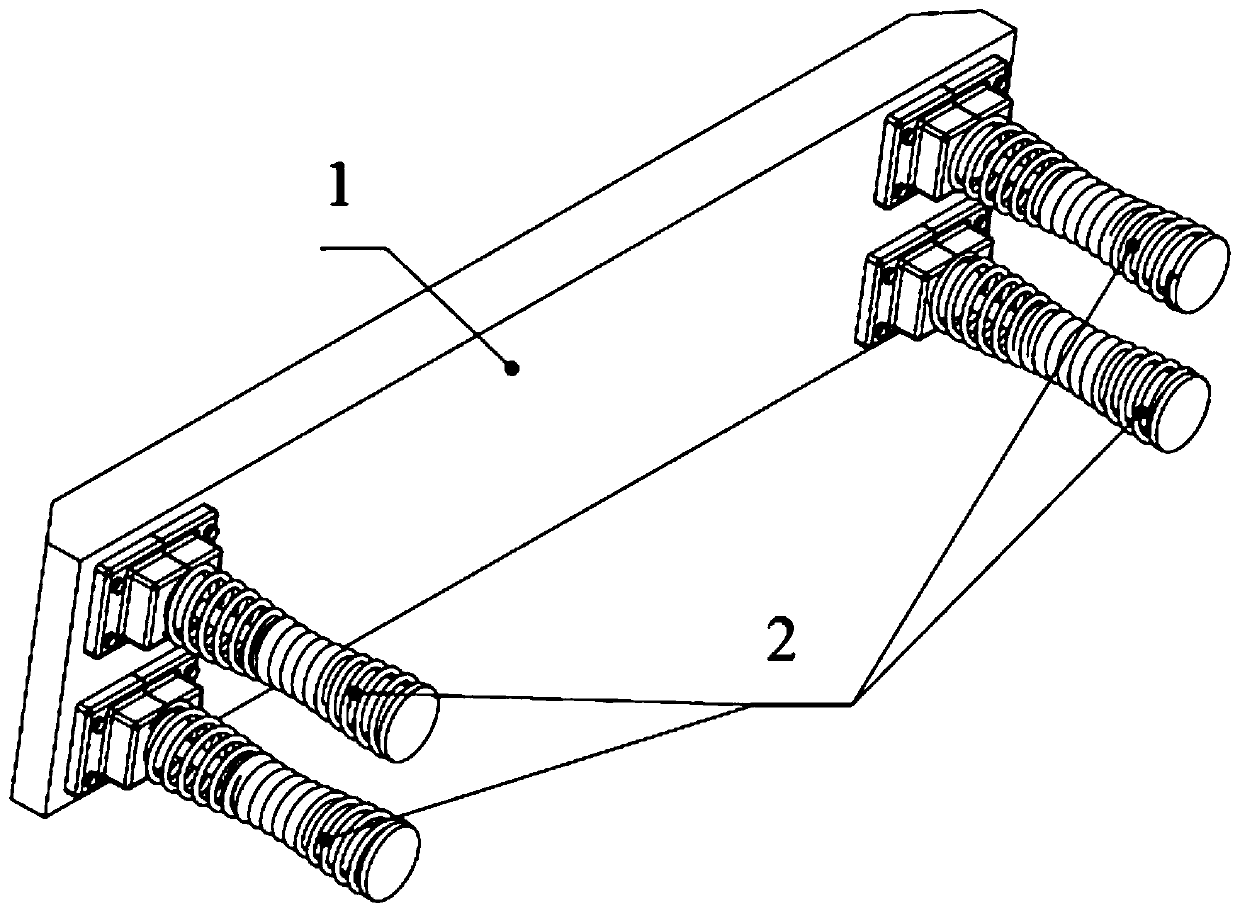
[0027] Such as figure 1 As shown, the front anti-collision beam assembly includes the front anti-collision beam body 1 and four collision energy-absorbing devices; the four collision energy-absorbing devices 2 are fixedly arranged on the same side of the front anti-collision beam body 1 through screw connections; The energy-absorbing device 2 is located at one end of the front anti-collision beam body 1 , and the other two energy-absorbing devices 2 are respectively located at the other end of the front anti-collision beam body 1 . The bolts connecting the anti-collision beam body and the collision energy-absorbing device can be quickly disassembled, and different specifications, models, and sizes of the front anti-collision beam body can be selected according to actual needs.

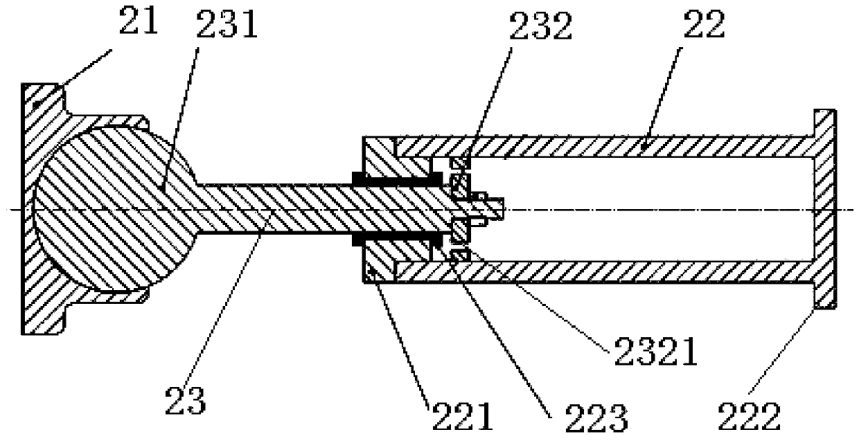
[0028] Such as figure 2 , image 3 As shown, the collision en...


PUM


Abstract

The invention relates to the technical field of vehicle parts, and provides a collision energy-absorbing device and a front anti-collision beam assembly in allusion to deficiency in a collision process that a collision contact area of a front anti-collision beam body and an obstacle is easily affected by a collapse route and a direction of an energy-absorbing box and the like. The collision energy-absorbing device comprises a ball base, a sleeve, a telescopic rod and a spring. One end of the sleeve is an opening end, and the other end is a non-opening end. The non-opening end is the closed sleeve bottom. One end of the telescopic rod is a spherical part, and the other end is provided with a piston. The spherical part is rotatably installed in the ball base. The piston is stretched into thesleeve through the opening end of the sleeve and reciprocated along a cavity of the sleeve relative to the sleeve bottom of the sleeve. An outer surface of the sleeve is fixedly provided with an outwards protruded support part. The support part is positioned at the non-opening end of the sleeve. The spring is sheathed on the telescopic rod and the sleeve, wherein one end thereof bears against theball base, and the other end bears against the support part.

Description

technical field [0001] The invention relates to the technical field of vehicle parts, in particular to a collision energy absorbing device and a front anti-collision beam assembly. Background technique [0002] At present, most of the vehicles used are traditional front anti-collision beam assemblies. The traditional front anti-collision beam assembly generally consists of a front anti-collision beam body and a crush-type energy-absorbing box, and the anti-collision beam body and the collapse-type energy-absorbing box are rigidly connected by welding or screwing. [0003] When the vehicle collides with an obstacle, the front anti-collision beam body of the traditional front anti-collision beam assembly moves toward the cab and causes the deformation and collapse of the energy-absorbing box. To achieve the purpose of energy absorption and anti-collision. [0004] However, due to the uncertain direction of the collision between the obstacle and the front anti-collision beam,...

Claims


Application Information

Patent Timeline
Patent Type & Authority Applications(China)
IPC IPC(8): B60R19/02B60R19/04B60R19/18B60R19/20
Inventor 李博张延京魏凯任文生魏宇刘佩康杨勇
Owner SHAANXI TONGJIA AUTOMOBILE
Why Eureka
Try Eureka