Floating frame device for medium-high voltage electronic aluminum production line and using method thereof

A production line, medium and high voltage technology, which is applied in the field of floating frame devices of medium and high voltage electronic aluminum production lines, can solve the problems of large floating frame devices, increased production line instability, and occupation of production line space, and achieves compact structure, simple structure, and improved The effect of product quality

Active Publication Date: 2021-06-01
GUANGXI HEZHOU GUIDONG ELECTRONICS TECH
View PDF23 Cites 1 Cited by
  • Summary
  • Abstract
  • Description
  • Claims
  • Application Information

AI Technical Summary

Problems solved by technology

At present, in order to ensure enough time for winding and changing operations, the traditional domestic floating rack equipment adopts multiple identical single-roller buffer devices connected in parallel to realize it, which not only leads to the increase in the size of the floating rack device and occupies the space of the production line, but also increases the production line. instability

Method used


Image

  • Floating frame device for medium-high voltage electronic aluminum production line and using method thereof
  • Floating frame device for medium-high voltage electronic aluminum production line and using method thereof
  • Floating frame device for medium-high voltage electronic aluminum production line and using method thereof

Examples


Embodiment 1

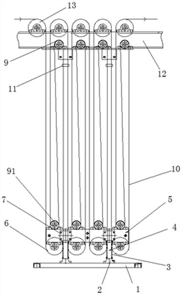
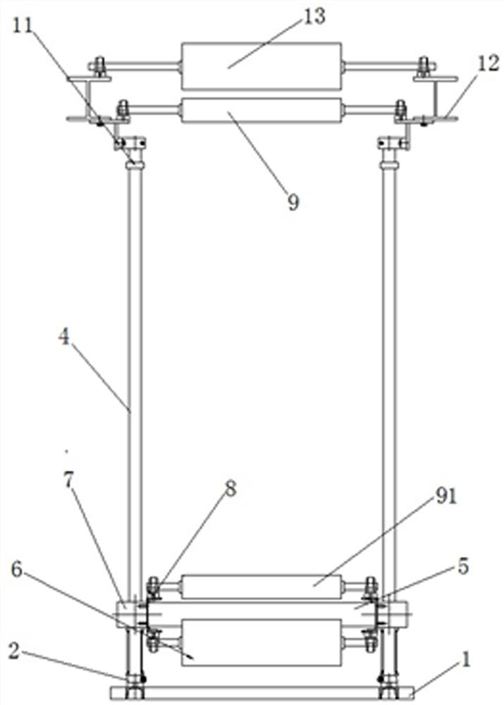
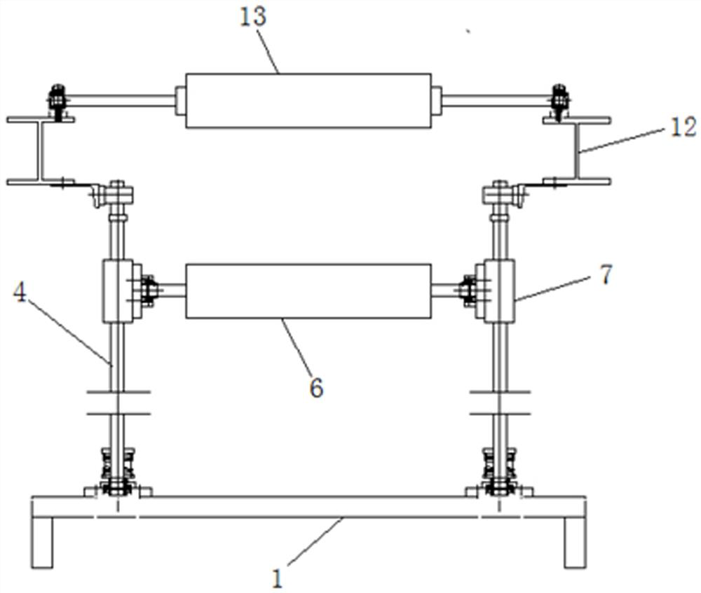
[0027] Such as Figure 1-4 As shown, a floating frame device for a medium and high voltage electronic aluminum production line in this embodiment includes a support frame 1 at the bottom, a guide shaft 4, a floating frame 5 and a roller beam 12; the two sides of the support frame 1 are respectively installed There is guide shaft 4, and the top of guide shaft 5 is provided with roller beam 12, and described roller beam 12 is parallel to supporting frame 1; The top of described roller beam 12 is uniformly distributed transition roller 13, and described transition roller The two ends of 13 are respectively connected to the roller beam 12 through the bearing housing 8; the transition roller 13 is parallel to the support frame 1; A9, the two ends of the small roller A9 are respectively connected to the roller beam 12 through the bearing housing 8, the small rollers A9 are arranged in parallel and adjacent to each other, and are placed directly below each transition roller 13; Desc...

Embodiment 2

[0029] The difference from Embodiment 1 is that: the guide shaft 4 between the floating frame 5 and the roller beam 12 is equipped with a limit block 11; the limit block 11 is movably connected with the guide shaft 4. The limit block 11 is used to limit the floating height of the floating frame 5 and prevent the floating frame 5 from colliding with the roller beam 12 .

Embodiment 3

[0031] The difference from Embodiment 2 is that: the bottom of the guide shaft 4 is provided with a spring member 3 . The spring member 3 is used to prevent the floating frame 5 from sliding downward under the action of gravity, hitting the support frame 1 and causing damage to the device.


PUM


Abstract

The invention discloses a floating frame device for a medium-high voltage electronic aluminum production line and a using method thereof. The floating frame device comprises a supporting frame, guide shafts, floating frames and a roller beam. The supporting frame is provided with the guide shafts, the roller beam is arranged at the tops of the guide shafts, transition rollers are uniformly distributed at the upper part of the roller beam, the two ends of each transition roller are respectively connected with the roller beam, the lower part of the roller beam is provided with small rollers A which are one less than the transition rollers, and the two ends of each small roller A are respectively connected with the roller beam. The floating frames are arranged in the middles of the guide shafts and are in sliding connection with the guide shafts through sliding blocks. The small rollers A are additionally arranged on the roller beam, large rollers and small rollers B are arranged on the floating frames to form a combination similar to a pulley block form, so that foil winding floating of the multiple sets of rollers is achieved. The foil winding mode of the large rollers, the small rollers A, the small rollers B, the transition rollers and the next set is adopted, the winding length of electronic aluminum foil is increased, the buffering time is prolonged, the foil winding structure is more compact, the occupied space of the foil winding structure is small, and meanwhile the stability of equipment is improved.

Description

technical field [0001] The invention belongs to the technical field of high-voltage electronic aluminum foil production line equipment, and in particular relates to a floating frame device of a medium-high voltage electronic aluminum production line and a method for using the same. Background technique [0002] With the rapid development of the electronics industry, the demand for electrode foils in related fields has increased sharply. At the same time, the automation of the production line for electrode foils is getting higher and higher and the foiling speed is getting faster and faster. This not only puts forward higher requirements for the stability of production line equipment Requirements, but also to ensure that there is enough time for changing rolls and winding operations. [0003] The floating frame slides up and down through the floating frame set on the buffer frame to win enough operating time for roll changing and winding to ensure continuous production. It is...

Claims


Application Information

Patent Timeline
Patent Type & Authority Applications(China)
IPC IPC(8): B21C47/02B21C47/26B21C47/28B21C47/34
CPCB21C47/02B21C47/26B21C47/28B21C47/34B21C47/345
Inventor 杨小飞蒋原华周俊文
Owner GUANGXI HEZHOU GUIDONG ELECTRONICS TECH
Why Eureka
Try Eureka