Laser distance measuring device and method for measuring distance between magnetic poles

A technology of laser distance measurement and spacing, which is applied in the directions of measuring devices, electromagnetic wave re-radiation, radio wave measurement systems, etc., which can solve the inconvenience of component installation and disassembly, maintenance and replacement, poor component protection effect, and poor monitoring accuracy and other problems to achieve the effect of convenient and quick measurement, avoiding errors, and preventing dust or muddy water from entering

Active Publication Date: 2021-12-03
NANJING ZEAHO ELECTRONICS TECH CO LTD
View PDF7 Cites 0 Cited by
  • Summary
  • Abstract
  • Description
  • Claims
  • Application Information

AI Technical Summary

Problems solved by technology

[0002] After the vehicle is loaded, the chassis of the vehicle will drop to different heights, corresponding to the different loads of the vehicle. According to this phenomenon, people have invented a distance measuring device to monitor the vehicle load, and it plays an important role in the logistics process. Function, it can prevent overloading or be used for data analysis of vehicle load. The damage and loss caused by overloaded transportation of trucks are shocking. The phenomenon of overloading has not improved. The signal or magnetic field of the existing distance measuring device interferes with the components during the measurement process. Many, the accuracy of distance measurement is not good, resulting in poor monitoring accuracy, the installation and disassembly of various components are inconvenient for maintenance and replacement, the protection effect of components is not good, and they are easy to be damaged. For this reason, we have introduced a measuring magnetic pole spacing Changing laser distance measuring device and its distance measuring method

Method used


Image

  • Laser distance measuring device and method for measuring distance between magnetic poles
  • Laser distance measuring device and method for measuring distance between magnetic poles
  • Laser distance measuring device and method for measuring distance between magnetic poles

Examples


Embodiment Construction

[0041] The following will clearly and completely describe the technical solutions in the embodiments of the present invention with reference to the accompanying drawings in the embodiments of the present invention. Obviously, the described embodiments are only some, not all, embodiments of the present invention. Based on the embodiments of the present invention, all other embodiments obtained by persons of ordinary skill in the art without making creative efforts belong to the protection scope of the present invention.

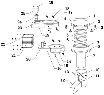
[0042] see figure 1 , Figure 5 , the present invention provides a technical solution: a laser distance measuring device for measuring the change of the magnetic pole spacing, including a shock absorber and a monitoring module, the shock absorber includes a shock absorbing piston cylinder 9 fixed to the wheel assembly, and a fixed fixed to the vehicle chassis. The flange seat 2 and the piston rod 5 at the output end of the shock-absorbing piston cylinder 9; t...


PUM


Abstract

The invention discloses a laser distance measuring device and a distance measuring method for measuring changes in magnetic pole spacing, including a shock absorber and a monitoring module. The shock absorber includes a shock absorbing piston cylinder fixed to a wheel assembly, and a fixing method fixed to a vehicle chassis The blue seat and the piston rod at the output end of the shock-absorbing piston cylinder, the piston rod is sleeved with a shock-absorbing spring; a square bellows is fixed between the upper support plate and the lower support plate, and a buffer spring is arranged inside the square bellows; the monitoring module includes The first Hall sensor, the second Hall sensor, the laser ranging sensor, and the lower end of the support spring are connected with an electrode block. The overall structure of the present invention occupies a small space and is convenient for disassembly and installation; the magnetic pole spacing is measured and calculated by two methods, which is convenient and quick to measure, and finally calculates the average value to obtain an accurate magnetic pole spacing, which can avoid errors caused by a single measurement method and improve Accuracy of vehicle load measurement.

Description

technical field [0001] The invention relates to the technical field of laser distance measuring devices, in particular to a laser distance measuring device and a distance measuring method for measuring changes in magnetic pole spacing. Background technique [0002] After the vehicle is loaded, the chassis of the vehicle will drop to different heights, corresponding to the different loads of the vehicle. According to this phenomenon, people have invented a distance measuring device to monitor the vehicle load, and it plays an important role in the logistics process. Function, it can prevent overloading or be used for data analysis of vehicle load. The damage and loss caused by overloaded transportation of trucks are shocking. The phenomenon of overloading has not improved. The signal or magnetic field of the existing distance measuring device interferes with the components during the measurement process. Many, the accuracy of distance measurement is not good, resulting in poo...

Claims


Application Information

Patent Timeline
Patent Type & Authority Patents(China)
IPC IPC(8): G01S17/10G01S7/481
CPCG01S17/10G01S7/481
Inventor 刘兆萄
Owner NANJING ZEAHO ELECTRONICS TECH CO LTD
Why Eureka
Try Eureka