Automatic loading and unloading device for PCBA manufacturing and production and operation method thereof

A technology of automatic loading and unloading and movable stop, which is applied in the direction of conveyor control device, transportation and packaging, object stacking, etc. It can solve the problems of affecting work efficiency, insufficient suction, and time-consuming limit correction, etc., and achieves the degree of automation high effect

Active Publication Date: 2019-05-24
广东中晨电子科技有限公司
View PDF9 Cites 14 Cited by
  • Summary
  • Abstract
  • Description
  • Claims
  • Application Information

AI Technical Summary

Problems solved by technology

[0003] In the process of using the existing automatic loading and unloading device for PCBA manufacturing and production, the piles of PCBAs cannot be adjusted as a whole. In each handling process, it is necessary to continuously adjust and position the suction lifting mechanism to carry out fixed handling; at the same time, different The size and area of ​​the PCBA are different, and when the suction cups of the suction lifting mechanism are used for adsorption and transportation, there will be insufficient suction caused by too many and too few suction cups and uneven distribution, and it is easy for the PCBA to fall during the handling process. ; At the same time, in the process of post-transporting the PCBA, the PCBA on the transmission mechanism cannot be well corrected and positioned, and it will take a lot of time to perform limit correction in the subsequent production process, which will affect work efficiency

Method used


Image

  • Automatic loading and unloading device for PCBA manufacturing and production and operation method thereof
  • Automatic loading and unloading device for PCBA manufacturing and production and operation method thereof
  • Automatic loading and unloading device for PCBA manufacturing and production and operation method thereof

Examples


Embodiment Construction

[0037] The technical solutions of the present invention will be clearly and completely described below in conjunction with the embodiments. Apparently, the described embodiments are only some of the embodiments of the present invention, not all of them. Based on the embodiments of the present invention, all other embodiments obtained by persons of ordinary skill in the art without creative efforts fall within the protection scope of the present invention.

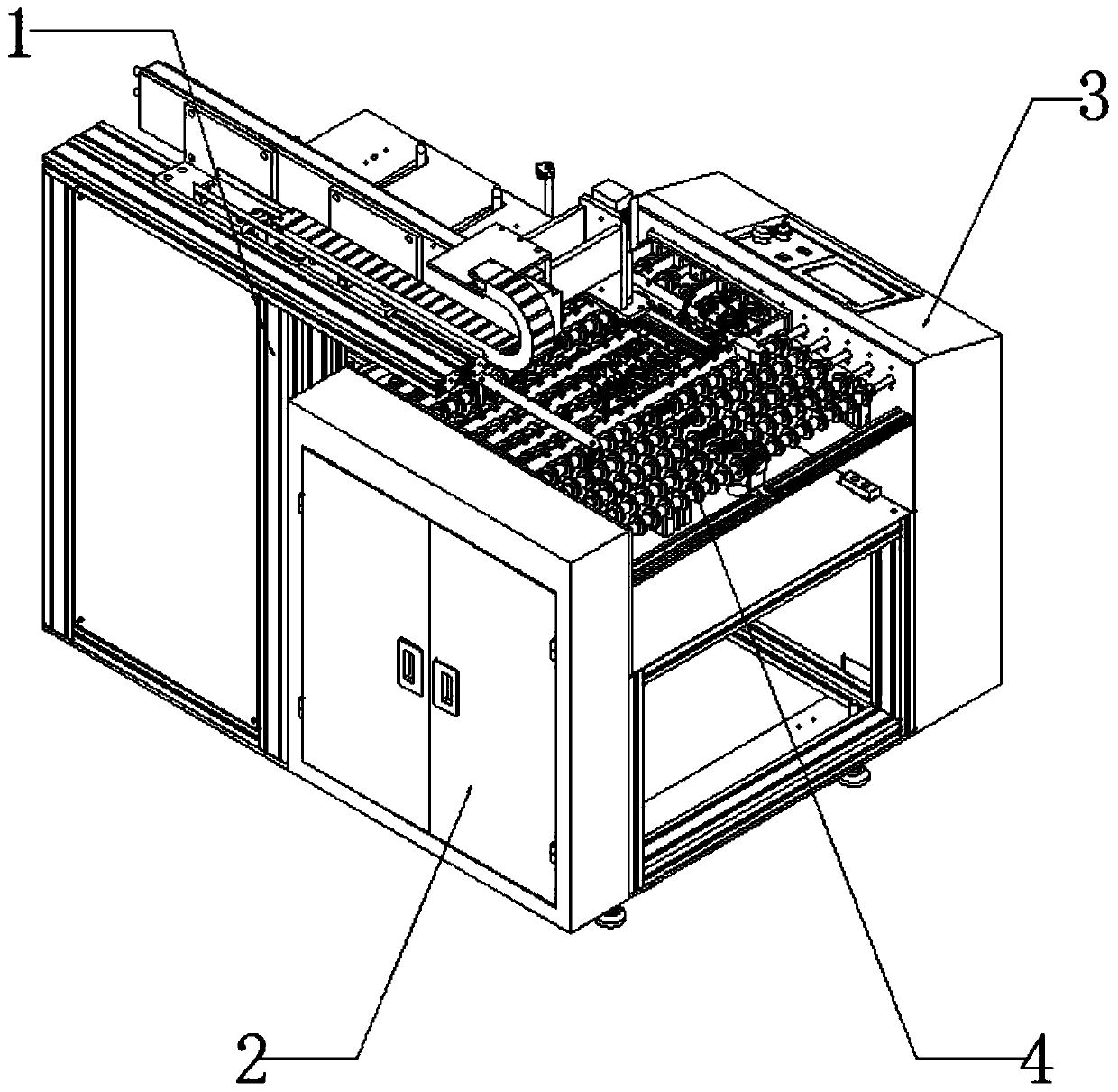
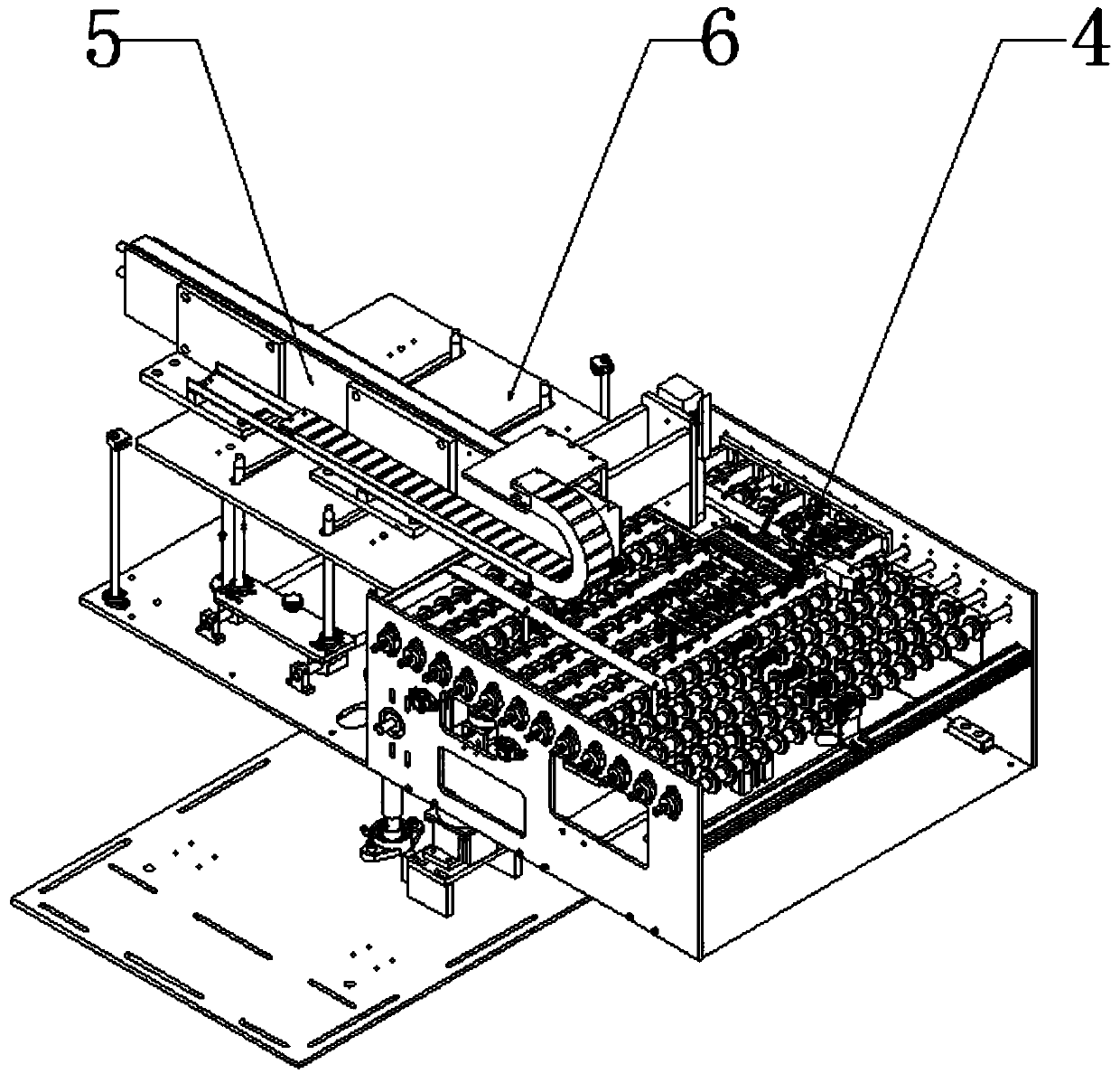
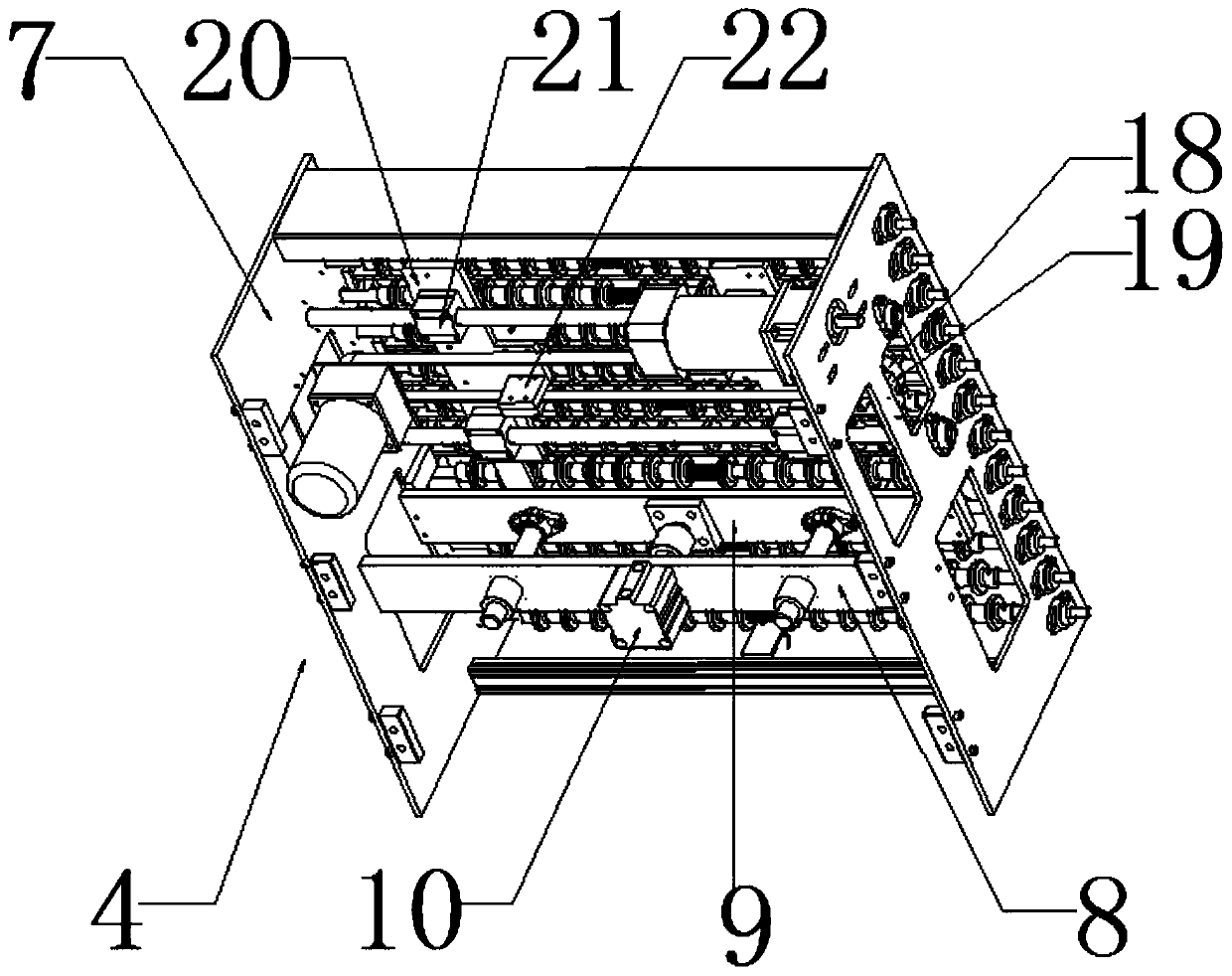
[0038] see Figure 1-9 As shown, an automatic loading and unloading device for PCBA manufacturing production, including a frame 1, an electric cabinet box 2, an electric control box 3, a discharge mechanism 4, a suction lifting mechanism 5 and a stacking mechanism 6, and one side of the frame 1 is installed with Electric cabinet box 2, an electric control box 3 is installed on the other side of the frame 1, a suction lifting mechanism 5 is installed on the top side of the frame 1, a discharge mechanism 4 is installed on the...


PUM


Abstract

The invention discloses an automatic loading and unloading device for PCBA manufacturing and production. The automatic loading and unloading device for the PCBA manufacturing and production comprisesa frame, an electric cabinet box, an electric cabinet, a discharging mechanism, a suction hanging mechanism and a stacking mechanism, wherein one side of the frame is provided with the electric cabinet box, the other side of the frame is provided with the electric cabinet, one side of the top of the frame is provided with the suction hanging mechanism, the inner side of the frame is provided withthe discharging mechanism, and one side adjacent to the frame is provided with the stacking mechanism; According to the invention, the piled PCBA is regulated on the whole, so that the transportationcan be carried out directly through positioning and adsorption of the suction hanging mechanism in each transportation process, and the automation degree is high; meanwhile, according to different sizes and areas of different PCBA, the position of a sucking disc can be planned and adjusted before the suction hanging mechanism is used, and when the suction carrying is carried out, the stable conveying can be completed by using the least sucking disc; the PCBA on a transmission mechanism is well calibrated and positioned to ensure that the subsequent manufacturing process can be directly operated.

Description

technical field [0001] The invention relates to the field of PCBA manufacturing equipment, in particular to an automatic loading and unloading device for PCBA manufacturing and an operating method thereof. Background technique [0002] Printed circuit board, also known as printed circuit board, printed circuit board, often uses the English abbreviation PCB, is an important electronic component, a support for electronic components, and a provider of circuit connections for electronic components. technology, so it is called a "printed" circuit board. Before the appearance of printed circuit boards, the interconnection between electronic components relied on the direct connection of wires to form a complete circuit. Now, the circuit breadboard only exists as an effective experimental tool, and the printed circuit board has become an absolute dominant position in the electronics industry; at the beginning of the 20th century, in order to simplify the production of electronic ma...

Claims


Application Information

Patent Timeline
Patent Type & Authority Applications(China)
IPC IPC(8): B65G47/91B65G59/04B65G61/00B65G43/00
Inventor 常小琼
Owner 广东中晨电子科技有限公司
Why Eureka
Try Eureka