
Installation structure for tower crane

An installation structure and tower crane technology, applied in cranes and other directions, can solve the problem that the tower crane foundation cannot be reused, etc., and achieve the effects of improving installation and demolition work efficiency, reducing environmental pollution and resource waste, and saving construction costs.

Inactive Publication Date: 2019-05-24
CHINA 19TH METALLURGICAL CORP
View PDF5 Cites 3 Cited by
  • Summary
  • Abstract
  • Description
  • Claims
  • Application Information

AI Technical Summary

Problems solved by technology

[0003] The technical problem to be solved by the present invention is to provide a tower crane installation structure, solve the problem that the existing tower crane foundation cannot be reused, improve the efficiency of tower crane installation and dismantling, reduce environmental pollution and resource waste caused by construction, and meet the requirements of green construction. Save construction cost

Method used


Image

  • Installation structure for tower crane
  • Installation structure for tower crane
  • Installation structure for tower crane

Examples


Embodiment Construction

[0023] The present invention will be further described below in conjunction with the accompanying drawings and embodiments.

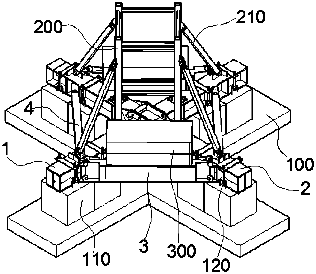
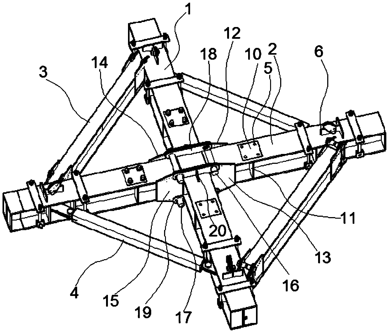
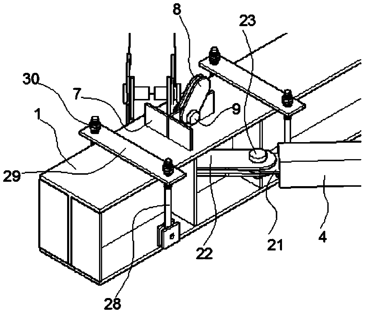
[0024] Tower crane installation structure of the present invention, as figure 1 , figure 2 , image 3 and Figure 4 As shown, including concrete foundation, steel structure foundation and tower crane,

[0025] Wherein, the concrete foundation includes a cross-shaped concrete slab 100 composed of 4 support plates, each of which is provided with a concrete pier 110 on the upper surface of the support plates; the 4 support plates of the concrete slab 100 are integrally formed, and each Two concrete piers 110 are naturally placed on the upper surface of the support plate. Specifically, the concrete slab 100 is a cross-shaped structure of 1.6m wide * 7.0m long * 0.2m thick, which is formed by pouring. When in use, the ground is directly leveled and placed on the ground to support other components. The concrete pier 110 is a square prefabricated concret...


PUM


Abstract

The invention discloses an installation structure for a tower crane. The installation structure for the tower crane comprises a concrete foundation, a steel structure foundation and a tower crane, wherein the concrete foundation comprises a cross-shaped concrete plate, and the upper surface of each support plate is provided with a concrete pier; the steel structure foundation comprises a long supporting beam and two short supporting beams; the long supporting beam and the short supporting beam are cross-shaped, and the ends of the long supporting beam and the short supporting beams are arranged on the upper surface of the concrete pier; a secondary beam is arranged between one side of the short supporting beams and the long supporting beam, a counterweight is arranged on the upper surfaceof the secondary beam, a pull beam is arranged between the other side of the short supporting beams and the long supporting beam, and tower crane positioning structures are arranged on the upper surfaces of the short supporting beams and the long supporting beam; the tower crane comprises a tower and an inclined stay bar; the tower and the inclined stay bar are installed on the steel structure foundation through the tower crane positioning structures. After the installation structure for the tower crane provided by the invention is adopted, a concrete platform does not need to be poured on site, the installation and disassembly work efficiency of the tower crane is improved, the environmental pollution and resource waste caused by construction are reduced, the requirement of green construction is met, and the construction cost is saved.

Description

technical field [0001] The invention relates to the field of tower cranes, in particular to a tower crane installation structure. Background technique [0002] The common method of tower crane foundation is to cast in-situ concrete foundation with large thickness, and there are also prefabricated assembly foundations. However, when the current method is used for construction, the volume of the poured concrete foundation is generally large, and it needs to go through the process of binding steel bars, supporting formwork, There are many processes such as pre-embedded bolts and pouring concrete. The construction period of the cast-in-place tower crane foundation is long. After the construction is completed, the foundation of the tower crane cannot be reused. The prefabricated and assembled foundation is heavy and inconvenient for transportation and installation. Obviously, the two methods have low construction efficiency, pollute the environment, cause a great waste of resourc...

Claims


Application Information

Patent Timeline
Patent Type & Authority Applications(China)
IPC IPC(8): B66C23/62
Inventor 王兆权毛兴平
Owner CHINA 19TH METALLURGICAL CORP
Learn More