Parking lock

A parking lock and lock lever technology, applied in the field of parking locks, can solve the problems of drive unit damage, inconvenient use, complicated operation, etc., and achieve the effect of improving the service life

Pending Publication Date: 2019-05-24
ROCKING ENERGY INTELLIGENT TECH CO LTD
View PDF11 Cites 2 Cited by
  • Summary
  • Abstract
  • Description
  • Claims
  • Application Information

AI Technical Summary

Problems solved by technology

These parking locks are of a great variety and have different structures. In the prior art, two support rods and bases are generally used to form a triangular structure erected, and the two support rods are locked by adding a U-shaped lock. This structure is complicated to operate and difficult to use. inconvenient
[0003] In addition, in the parking lock in the prior art, when the stop arm is forcibly suppressed by external force, the stop arm will drive the drive unit to rotate, easily causing damage to the drive unit, increasing the risk of damage to the drive unit, and affecting the service life of the parking lock

Method used


Image

  • Parking lock
  • Parking lock
  • Parking lock

Examples


Embodiment 1

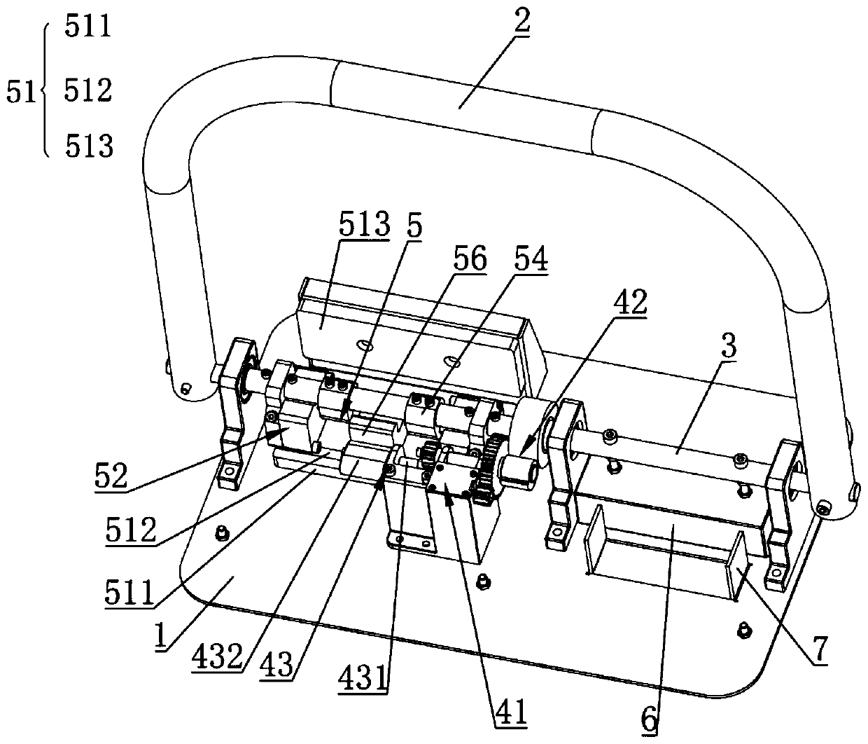
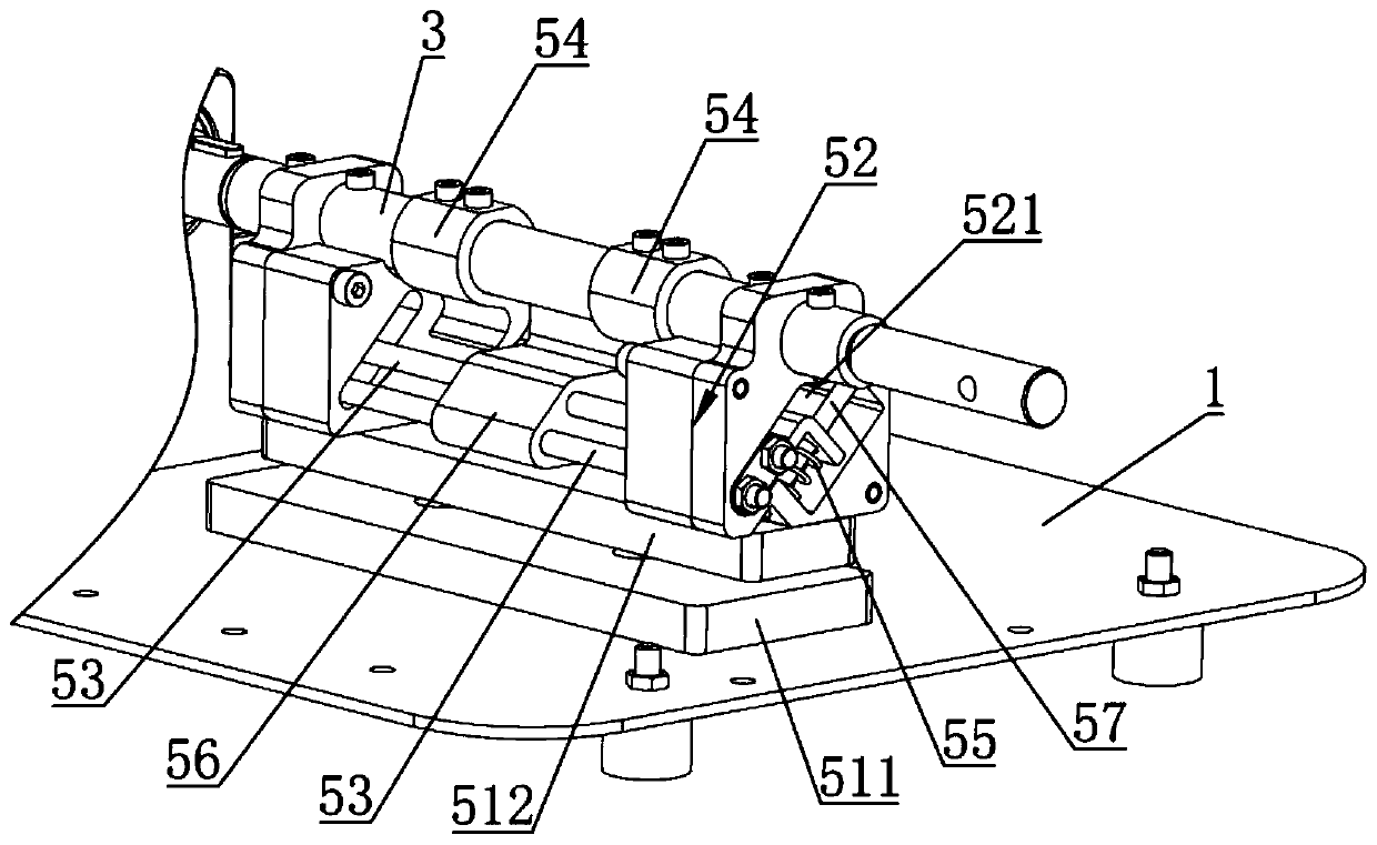
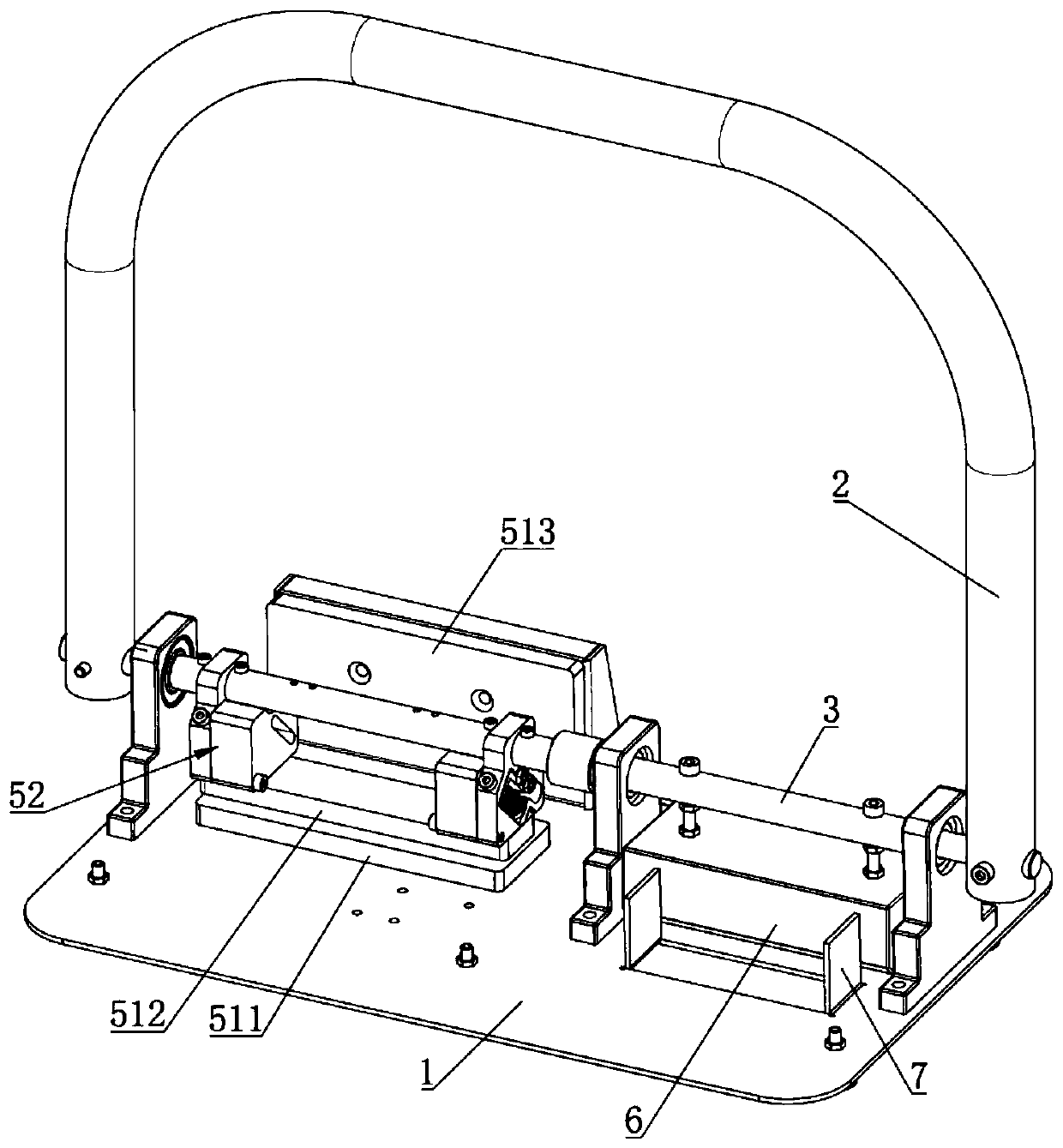
[0036] refer to Figure 1~5 , the present embodiment provides a parking lock, comprising a base 1, a blocking arm 2, a rotating shaft 3, a driving mechanism 4 and a locking mechanism 5 arranged on the base 1, the rotating shaft 3 is rotatably erected on the base 1, the blocking arm 2 and the The rotating shaft 3 is fixedly connected. The driving mechanism 4 includes a driving unit 41 and a clutch assembly 42. The driving unit 41 is connected to the rotating shaft 3 through the clutch assembly 42. The locking mechanism 5 includes a limiting assembly 51, a limiting member 52 and a locking rod 53. The position member 52 is connected to the rotating shaft 3 in rotation, the limit assembly 51 is respectively connected to the limit member 52 and the base 1, the rotating shaft 3 is fixedly connected to the stop member 54, and the locking rod 53 is installed on the limit member 52 and arranged on the rotation path of the stop member 54 In the interference position, the driving unit 41...

Embodiment 2

[0057] refer to Figure 6 ~ Figure 8 The difference between this embodiment and Embodiment 1 is that the locking lever 53 includes a link portion 531 and an interference portion 532, one end of the link portion 531 is connected to the interference portion 532, and the other end is rotatably connected to the stopper 52, and the interference portion 532 Set at the interference position of the rotation path of the stopper 54, the drive unit 41 is connected with the link part 531. In the locked state, the lock lever 53 is set at the interference position of the rotation path of the stopper 54, so that the stopper arm 2 can , the stop arm 2 drives the rotating shaft 3 to rotate, and the stop member 54 drives the lock bar 53 to rotate. Since the lock bar 53 is installed on the limiter 52, its limiter 52 and the limiter assembly 51 are connected with the base 1 in sequence, so that the limiter 52 The activity is limited by the limit assembly 51, so as to achieve the effect of limitin...

Embodiment 3

[0061] refer to Figure 9 ~ Figure 14 The difference between this embodiment and Embodiment 1 is that the eccentric assembly 43 includes a transmission shaft 431, an eccentric wheel 432 and an eccentric rod 433, the transmission shaft 431 is coaxially arranged with the eccentric rod 433, and the eccentric rod 433 is connected to the eccentric wheel 432 and connected to the eccentric The wheel 432 is set eccentrically, the eccentric rod 433 is in contact with the lock rod 53, the transmission shaft 431 is connected to the drive unit 41, and the rotating shaft 3 drives the eccentric wheel 432 to rotate, thereby driving the eccentric rod 433 to rotate, and the eccentric rod 433 moves the guide block 56 to drive The locking bar 53 moves so that the locking bar 53 avoids the interference position where the blocking member 54 rotates.

[0062] In addition, the transmission part 424 is meshed with the driven wheel 421, the transmission efficiency of the meshing transmission is high, ...


PUM


Abstract

The invention relates to a parking lock. The parking lock comprises a base, a stop arm, a rotating shaft, a driving mechanism and a locking mechanism, wherein the driving mechanism and the locking mechanism are arranged on the base, the rotating shaft can be rotatably erected on the base, and the stop arm is fixedly connected to the rotating shaft. The driving mechanism comprises a driving unit and an engaging-disengaging component, and the driving unit is in drive connection with the rotating shaft through the engaging-disengaging component. The locking mechanism comprises a limiting component and a lock rod, the limiting component is mounted on the base, the rotating shaft is fixedly connected to a stopper, the lock rod is arranged at an interference position of the stopper rotation pathand is connected to the limiting component, and the driving unit is connected to the lock rod for driving the lock rod to leave the interference position of the stopper rotation path. The parking lock has the advantages that damage of the driving unit is reduced through the engaging-disengaging component, so that the service life of the parking lock is prolonged; the locking mechanism is used forunlocking and locking the stop arm, the limiting component is used for limiting the stop arm to move in the locking state, and accordingly usage reliability of the parking lock is enhanced.

Description

technical field [0001] The invention relates to the technical field of parking locks, in particular to a parking lock. Background technique [0002] With the development of the economy and the improvement of people's material living standards, cars have entered more and more ordinary families. With the increase of per capita car ownership, the problem of fewer parking spaces and difficult parking has become more and more prominent, especially in some parking spaces. The problem of parking is particularly prominent in old communities with a small number of buildings and commercial buildings with a high density of vehicles. Sometimes even rented or purchased parking spaces will be "temporarily" occupied by people, but there is nowhere to park your car. In order to ensure that one has a parking space to park, many parking locks for occupying parking spaces have appeared on the market. These parking locks are of a great variety and have different structures. In the prior art, ...

Claims


Application Information

Patent Timeline
Patent Type & Authority Applications(China)
IPC IPC(8): E04H6/42E01F13/08
Inventor 钟荣栋其他发明人请求不公开姓名
Owner ROCKING ENERGY INTELLIGENT TECH CO LTD
Why Eureka
Try Eureka