A vane pump drying auxiliary device

An auxiliary device and vane pump technology, which is applied in the direction of drying gas arrangement, heating device, drying solid materials, etc., can solve the problems of poor practicability, low efficiency, and low cleanliness

Active Publication Date: 2020-10-27
江西中超泵业有限公司
View PDF6 Cites 0 Cited by
  • Summary
  • Abstract
  • Description
  • Claims
  • Application Information

AI Technical Summary

Problems solved by technology

[0002] As we all know, the vane pump drying auxiliary device is an auxiliary device for drying cone-shaped bucket parts, which has been widely used in the field of mechanical processing; the existing vane pump drying auxiliary device also includes mounting plates, mounting plates The middle part is provided with a through hole that penetrates up and down, and the mounting plate is provided with a fixing device; when the existing vane pump drying auxiliary device is used, the external cone-shaped bucket-shaped part is first placed on the mounting plate, and then the cone is fixed by the fixing device. The bucket-shaped part is fixed, and then the cone-shaped bucket-shaped part is naturally air-dried; in the use of the existing vane pump drying auxiliary device, it is found that there is more residual water on the cone-shaped bucket-shaped part, and the drying time is longer, resulting in a high efficiency. Low; and the inside of the cone-shaped bucket part is easy to accumulate dust during the drying process, resulting in a low degree of cleaning and poor practicability; and the internal humidity of the cone-shaped bucket-shaped part after drying is high, which is easy to make the cone-shaped bucket rusty parts, resulting in lower reliability

Method used


Image

  • A vane pump drying auxiliary device
  • A vane pump drying auxiliary device
  • A vane pump drying auxiliary device

Examples


Embodiment Construction

[0019] The specific implementation manners of the present invention will be further described in detail below in conjunction with the accompanying drawings and embodiments. The following examples are used to illustrate the present invention, but are not intended to limit the scope of the present invention.

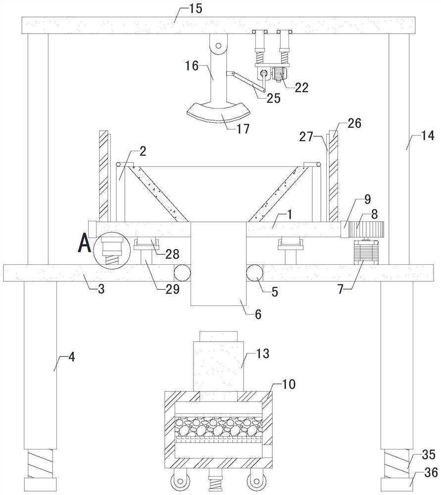
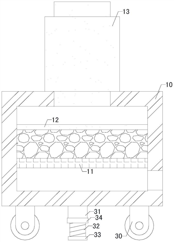
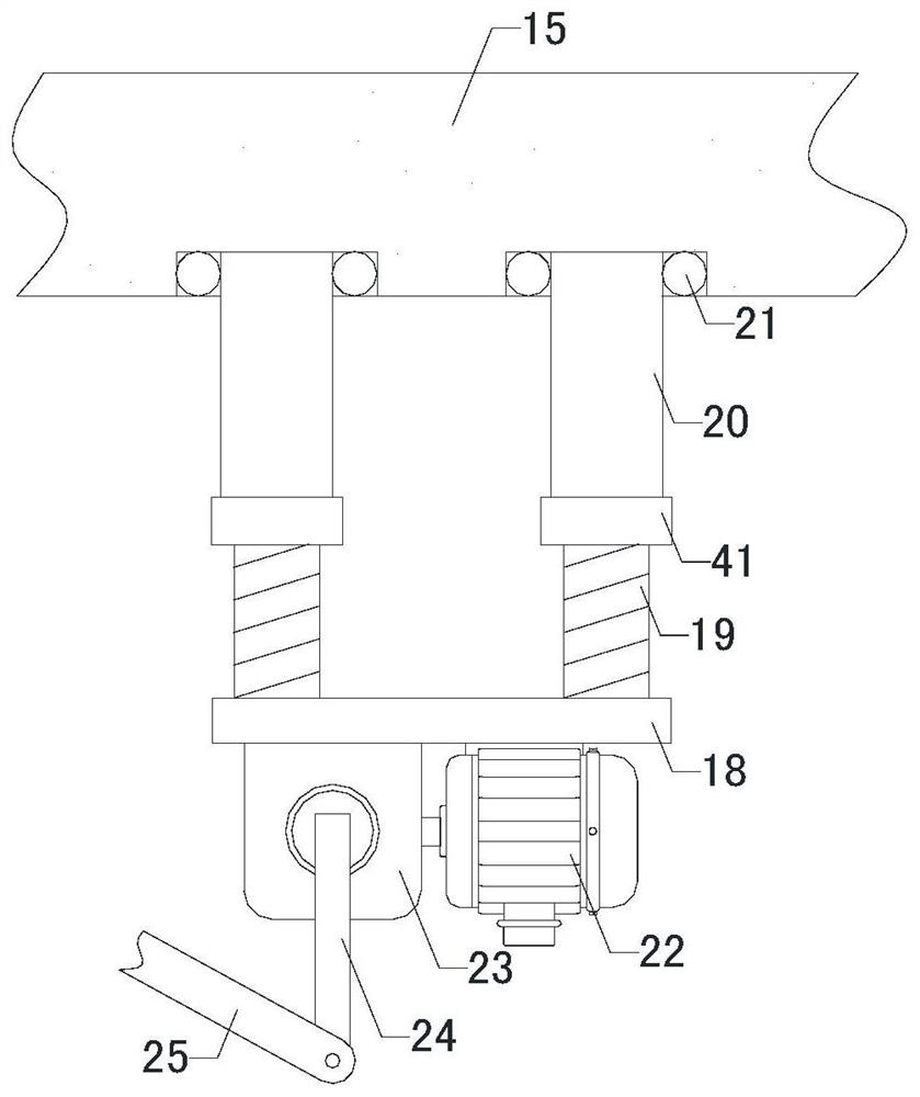
[0020] Such as Figure 1 to Figure 4As shown, a vane pump drying auxiliary device of the present invention also includes a mounting plate 1, the middle part of the mounting plate 1 is provided with a through hole penetrating up and down, and the mounting plate 1 is provided with a fixing device 2; it also includes a bottom plate 3, four sets of Support legs 4, air pipe 6, power motor 7 and gear ring 9, the left front side, left rear side, right front side and right rear side of the bottom of the bottom plate 3 are respectively connected with the tops of the four sets of support legs 4, and the middle part of the bottom plate 3 is provided with Placement hole, the first ba...


PUM


Abstract

The invention relates to the technical field of machining, in particular to a vane pump drying auxiliary device. Residual water on a taper-hopper-shaped part is reduced, drying time is shortened, andworking efficiency is improved; the occurrence of the condition that dust is accumulated inside the taper-hopper-shaped part during the process of drying is reduced, cleanlinessis improved, and practicability is improved; the occurrence of rusting of the taper-hopper-shaped part is reduced, and application reliability is improved; the vane pump drying auxiliary device further comprises an installation plate, a through hole penetrating up and down is formed in the middle part of the installation plate, and a fixing device is arranged on the installation plate; the vane pump drying auxiliary device further comprises a baseboard, four groups of supporting legs, a breather pipe, a power motor and a ring gear; the vane pump drying auxiliary device further comprises an accommodation chamber, a cavity is formed in the accommodation chamber, and a right opening is formed in the lower side of the right end of the accommodation chamber; and the vane pump drying auxiliary device further comprisesfour groups of supporting rods, a top plate, a connecting rod, a drying light, a rack plate, four groups of threaded rods, four groups of threaded pipes, an angle adjusting motor, a speed reducer, afirst transmission rod and a second transmission rod.

Description

technical field [0001] The invention relates to the technical field of mechanical processing, in particular to a vane pump drying auxiliary device. Background technique [0002] As we all know, the vane pump drying auxiliary device is an auxiliary device for drying cone-shaped bucket parts, which has been widely used in the field of mechanical processing; the existing vane pump drying auxiliary device also includes mounting plates, mounting plates The middle part is provided with a through hole that penetrates up and down, and the mounting plate is provided with a fixing device; when the existing vane pump drying auxiliary device is used, the external cone-shaped bucket-shaped part is first placed on the mounting plate, and then the cone is fixed by the fixing device. The bucket-shaped part is fixed, and then the cone-shaped bucket-shaped part is naturally air-dried; in the use of the existing vane pump drying auxiliary device, it is found that there is more residual water o...

Claims


Application Information

Patent Timeline
Patent Type & Authority Patents(China)
IPC IPC(8): F26B5/08F26B21/08F26B23/04F26B25/00
Inventor 卓业伦吴金潭
Owner 江西中超泵业有限公司
Why Eureka
Try Eureka