Fishing bait throwing machine

A technology of fishing bait and driving motor, which is applied in the field of throwing machines, can solve the problems of arm soreness, trouble, uneven throwing of fishing bait, etc., and achieve the effect of avoiding arm soreness.

Active Publication Date: 2019-05-28
新昌县城丹服装有限公司
View PDF2 Cites 9 Cited by
  • Summary
  • Abstract
  • Description
  • Claims
  • Application Information

AI Technical Summary

Problems solved by technology

[0002] In aquaculture, there are all kinds of aquatic products, and fish is one of them. In order to ensure the healthy growth of fish, people need to regularly throw bait into fish ponds for fish to eat. Throwing the bait into the fish pond requires constant waving of the arm. Over time, the human arm is prone to soreness and affects the follow-up work, and feeding the fish in the distance requires forceful throwing, which is troublesome, so people will throw the bait directly at one time. In the fish pond, the fish in the distance are fed by boat, so it is easy to cause the bait to be thrown unevenly and become half-height

Method used


Image

  • Fishing bait throwing machine
  • Fishing bait throwing machine
  • Fishing bait throwing machine

Examples


Embodiment 1

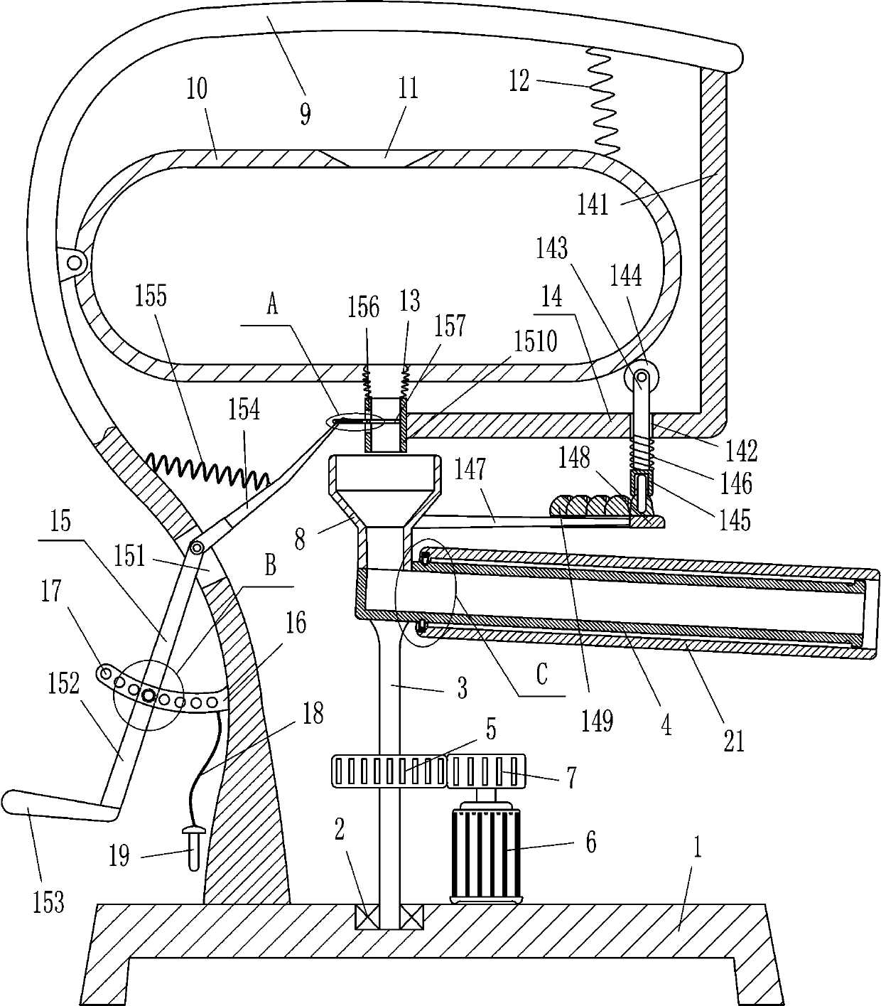
[0018] A bait casting machine, such as Figure 1-2 As shown, it includes a base 1, a first bearing seat 2, a first rotating shaft 3, a discharge pipe 4, a first gear 5, a driving motor 6, a second gear 7, a lower hopper 8, a 7-shaped plate 9, and a box body 10 , the first spring 12, the bellows 13 and the pushing device 14, the first bearing seat 2 is embedded on the left side of the top of the base 1, the first rotating shaft 3 is connected with the bearing in the first bearing seat 2, and the first rotating shaft 3 passes through The way of interference connection is connected with the bearing in the first bearing seat 2, and the discharge pipe 4 that can discharge the bait can be installed on the top of the first rotating shaft 3. The left side of the top of the discharge pipe 4 is fixedly connected with the lower hopper 8, and the discharge pipe 4 is connected with the lower hopper 8 through bolt connection, the lower hopper 8 communicates with the discharge pipe 4, the fi...

Embodiment 2

[0020] A bait casting machine, such as Figure 1-2 As shown, it includes a base 1, a first bearing seat 2, a first rotating shaft 3, a discharge pipe 4, a first gear 5, a driving motor 6, a second gear 7, a lower hopper 8, a 7-shaped plate 9, and a box body 10 , the first spring 12, the bellows 13 and the pushing device 14, the first bearing seat 2 is embedded in the left side of the top of the base 1, the first rotating shaft 3 is connected with the bearing in the first bearing seat 2, and the bait can be discharged The discharge pipe 4 is installed on the top of the first rotating shaft 3, the left side of the top of the discharge pipe 4 is fixedly connected with the lower hopper 8, the lower hopper 8 communicates with the discharge pipe 4, the first gear 5 is installed in the middle of the first rotating shaft 3, and the driving The motor 6 is bolted to the right side of the top of the base 1, the output shaft of the drive motor 6 is connected to the second gear 7 through a...

Embodiment 3

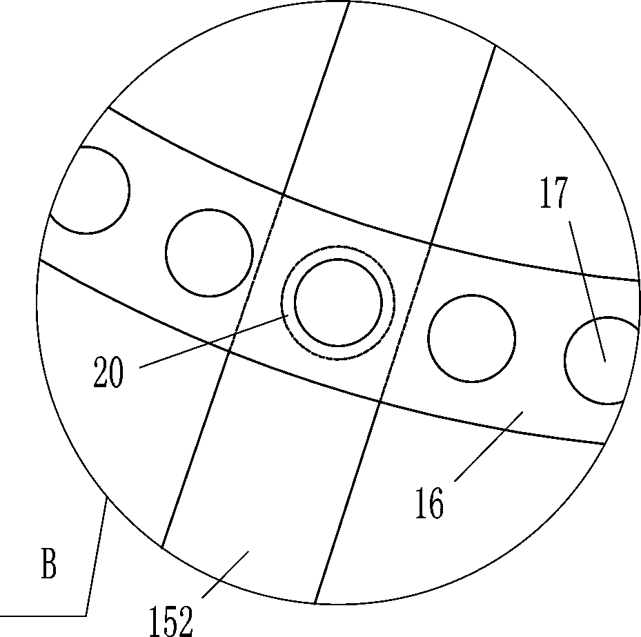
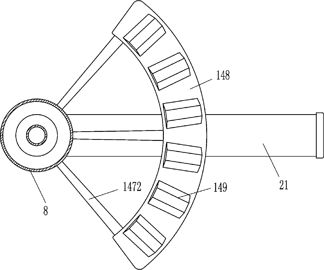
[0023] A bait casting machine, such as Figure 1-3As shown, it includes a base 1, a first bearing seat 2, a first rotating shaft 3, a discharge pipe 4, a first gear 5, a driving motor 6, a second gear 7, a lower hopper 8, a 7-shaped plate 9, and a box body 10 , the first spring 12, the bellows 13 and the pushing device 14, the first bearing seat 2 is embedded in the left side of the top of the base 1, the first rotating shaft 3 is connected with the bearing in the first bearing seat 2, and the bait can be discharged The discharge pipe 4 is installed on the top of the first rotating shaft 3, the left side of the top of the discharge pipe 4 is fixedly connected with the lower hopper 8, the lower hopper 8 communicates with the discharge pipe 4, the first gear 5 is installed in the middle of the first rotating shaft 3, and the driving The motor 6 is bolted to the right side of the top of the base 1, the output shaft of the drive motor 6 is connected to the second gear 7 through a ...


PUM


Abstract

The invention relates to a throwing machine, in particular to a fishing bait throwing machine. The fishing bait throwing machine is capable of throwing baits evenly into a fish pond instead of manualwork, avoids influence of the subsequent work caused by the pain of arms, and can feed fish in the distant place. According to the technical scheme, the fishing bait throwing machine comprises a base,a first bearing seat, a first rotating shaft, a discharging pipe, a first gear, a driving motor, a second gear, a feeding hopper, a 7-shaped plate, a box body, a first spring and the like, the firstbearing seat is installed on the left side of the top of the base in an embedded mode, and the first rotating shaft is connected with a bearing in the first bearing seat. The fishing bait throwing machine puts the baits into the box body and starts the driving motor, so that the baits can be evenly throwing through the discharging pipe to the fish pond for the fish to eat without the need for people to constantly wave arms to throw the baits into the fish pond, time and effort are saved, and the pain of the arms is avoided.

Description

technical field [0001] The invention relates to a throwing machine, in particular to a fishing bait throwing machine. Background technique [0002] In aquaculture, there are all kinds of aquatic products, and fish is one of them. In order to ensure the healthy growth of fish, people need to regularly throw bait into fish ponds for fish to eat. Throwing the bait into the fish pond requires constant waving of the arm. Over time, the human arm is prone to soreness and affects the follow-up work, and feeding the fish in the distance requires forceful throwing, which is troublesome, so people will throw the bait directly at one time. In the fish pond, the fish in the distance are fed by boat, so it is easy to cause the bait to be thrown unevenly and become half-height. Contents of the invention [0003] In order to overcome the shortcomings that people need to constantly wave their arms to throw bait, over time, people’s arms are prone to soreness and affect follow-up work, an...

Claims


Application Information

Patent Timeline
Patent Type & Authority Applications(China)
IPC IPC(8): A01K61/80
CPCY02A40/81
Inventor 林炳荣
Owner 新昌县城丹服装有限公司
Why Eureka
Try Eureka