self-service eye dropper
An eye dropper and horizontal support technology, which is applied in ophthalmic treatment, medical equipment, etc., can solve the problems of small squeezing range, adults who are not necessarily easy to instill eye drops correctly, and ineffective eye drops
- Summary
- Abstract
- Description
- Claims
- Application Information
AI Technical Summary
Problems solved by technology
Method used
Image
Examples
Embodiment 1
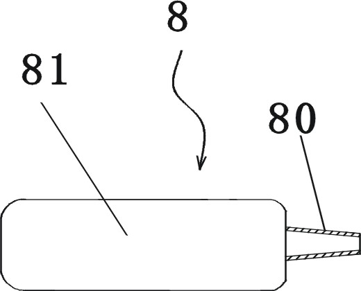
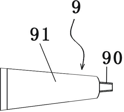
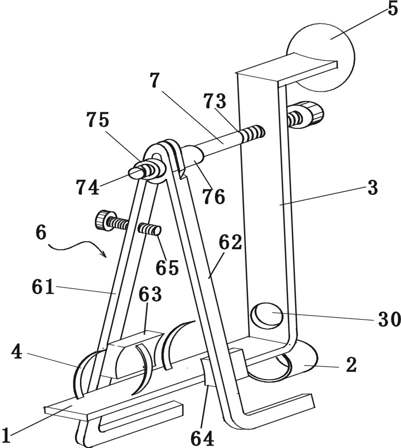
[0041] image 3 , Figure 4 , Figure 5 The structure shown is a self-service eye dropper. The self-service eye dropper includes a long horizontal support plate 1. The following describes the self-service eye dropper with the horizontal support plate 1 in a horizontal and vertical direction. structure. A finger sleeve 2 for clamping a finger is fixed under the front section of the elongated horizontal support plate 1, and a vertical connector 3 is fixed above the front section of the horizontal support plate 1, and the vertical connector 3 is provided with a container The hollow hole 30 through which the mouth passes, the distance between the center point of the hollow hole 30 and the upper surface of the horizontal support plate 1 (such as Figure 4 The middle dimension line h) is 10mm; above the horizontal support plate 1, there is also an elastic clip 4 for clamping the body of the eye medicine container. The elastic clip 4 fits left and right to clamp the body of the eye med...
Embodiment 2
[0053] There are three main differences between the second embodiment and the first embodiment. The three differences make the second embodiment particularly suitable for eye drops. The three main differences are as follows:
[0054] The difference in the first aspect: the longitudinal limiting member 5 of the second embodiment is a circular roller, and the rotating shaft 51 of the circular roller is vertical; the rotating shaft 51 of the circular roller is installed in the connector assembly (the longitudinal connector and the vertical The upper part of the connecting piece is called the connecting piece assembly); the circular roller 5 is provided with an arc-shaped hole 50 at an eccentric position, and one side edge of the arc-shaped hole 50 is provided with a small magnet 53 and a through hole Into the vertical iron pin 52 of the arc-shaped hole 50, the lower end of the vertical iron pin 52 is fixedly connected to the connecting piece assembly, such as Picture 9 , Picture 10...
PUM
 Abstract
Description
Claims
Application Information
 - R&D
- Intellectual Property
- Life Sciences
- Materials
- Tech Scout
- Unparalleled Data Quality
- Higher Quality Content
- 60% Fewer Hallucinations
Browse by: Latest US Patents, China's latest patents, Technical Efficacy Thesaurus, Application Domain, Technology Topic, Popular Technical Reports.
© 2025 PatSnap. All rights reserved.Legal|Privacy policy|Modern Slavery Act Transparency Statement|Sitemap|About US| Contact US: help@patsnap.com


