
Fixed-point ion implantation device and implantation method for a substrate
A technology of ion implantation device and substrate, applied in the directions of circuits, discharge tubes, electrical components, etc., can solve the problem of no fixed-point implantation, etc., and achieve the effect of precise positioning
- Summary
- Abstract
- Description
- Claims
- Application Information
AI Technical Summary
Problems solved by technology
Method used
Image

Examples
Embodiment 1
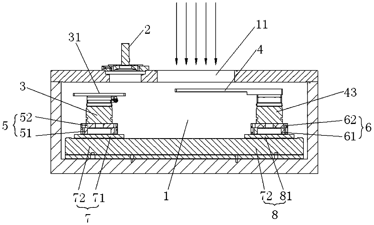
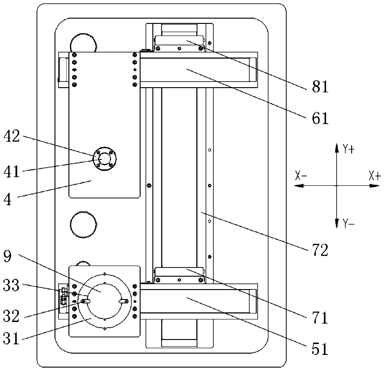
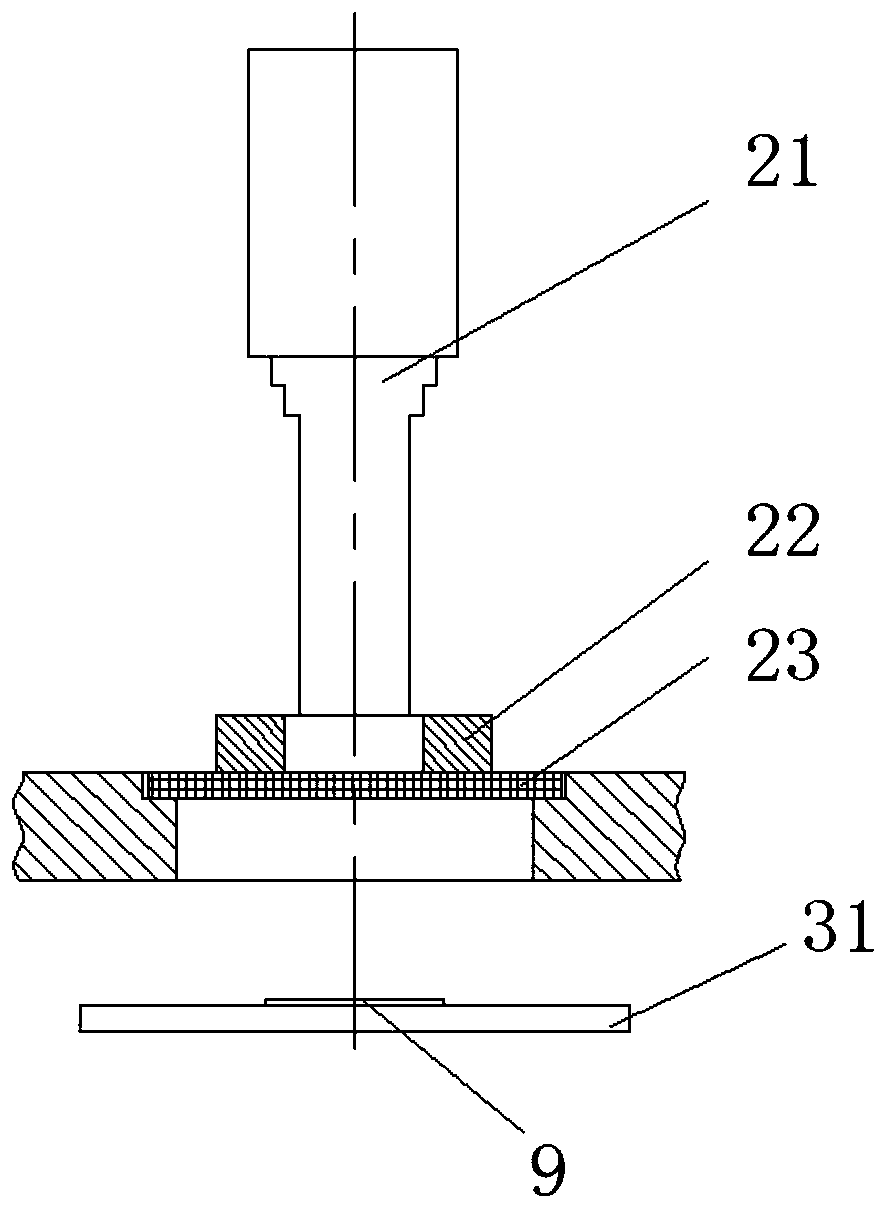
[0033] Such as Figure 1 to Figure 4 As shown, the fixed-point ion implantation device of the substrate of the present embodiment includes a control unit, a vacuum chamber 1, a substrate positioning device arranged in the vacuum chamber 1 and a machine vision system 2 arranged outside the vacuum chamber 1, The substrate positioning device includes a substrate holder 3, a cover plate 4, a first X-axis moving mechanism 5, a second X-axis moving mechanism 6, a first Y-axis moving mechanism 7, and a second Y-axis moving mechanism 8. The first X-axis The moving mechanism 5 is arranged on the first Y-axis moving mechanism 7, the second X-axis moving mechanism 6 is arranged on the second Y-axis moving mechanism 8, the substrate holder 3 is arranged on the first X-axis moving mechanism 5, and the cover plate 4 Set on the second X-axis moving mechanism 6, the substrate 9 is fixed on the substrate holder 3, the mask plate 4 is provided with a beam flow hole 41, and the machine vision sy...
PUM
 Abstract
Description
Claims
Application Information