
Automatic cleaning method for liquefied gas steel cylinder

An automatic cleaning and liquefied gas technology, applied in cleaning methods and utensils, chemical instruments and methods, cleaning hollow objects, etc., can solve the problems of time-consuming, labor-intensive, low efficiency, and inability to judge the liquefied gas cylinder logo from the appearance, etc. Cleaning efficiency, the effect of fully automated cleaning

Inactive Publication Date: 2019-05-28
绍兴恒研机电科技有限公司
View PDF10 Cites 2 Cited by
  • Summary
  • Abstract
  • Description
  • Claims
  • Application Information

AI Technical Summary

Problems solved by technology

[0002] The liquefied gas cylinder is a kind of steel cylinder for storing liquefied gas. Since it is usually placed near the kitchen gas stove when in use, its surface is easily contaminated with various oils. If it is not cleaned in time, it will lead to accelerated corrosion of the liquefied gas cylinder, and it cannot be removed from the Judging the mark on the surface of the liquefied gas cylinder by the appearance, which will bring inconvenience to the maintenance and bury safety problems
[0003] At present, most gas stations generally adopt manual cleaning. Due to the weight of the liquefied gas cylinder itself (general household steel cylinder weighs about 15 kilograms), manual cleaning is very time-consuming and laborious, and the efficiency is low; the existing prior patent CN204122428, although also A cleaning device is disclosed, but it is only an idea, and those skilled in the art cannot realize the solution according to its specific embodiment, while the prior patent CN205128541 discloses only a cleaning device for a single steel cylinder. The efficiency of cleaning is still not high: Paragraph 0018 of the instruction manual, manual support is required during the cleaning process

Method used


Image

  • Automatic cleaning method for liquefied gas steel cylinder
  • Automatic cleaning method for liquefied gas steel cylinder
  • Automatic cleaning method for liquefied gas steel cylinder

Examples


Embodiment Construction

[0035] The present invention will be further described below in conjunction with the accompanying drawings and specific embodiments.

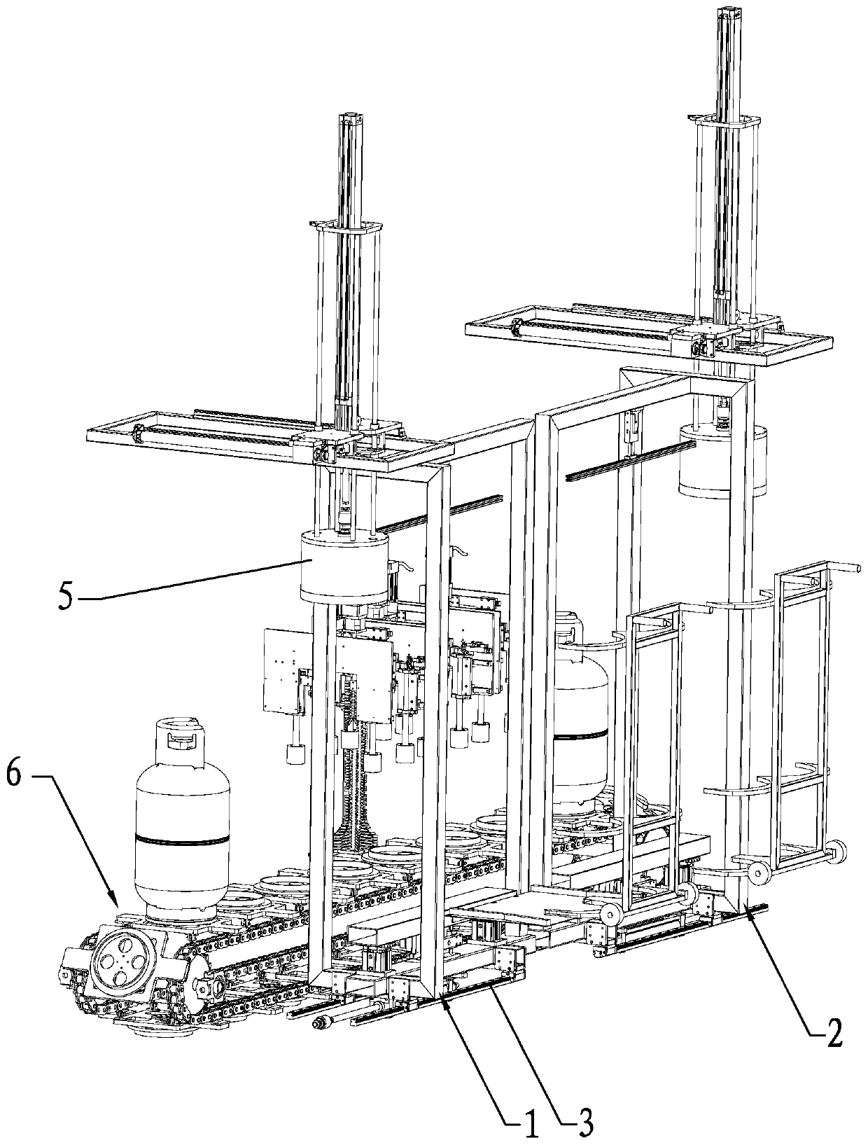
[0036] Existing cylinder carts such as Figure 4 As shown, by setting the matching semi-circular support at the bottom of the steel cylinder, the steel cylinder can be transported after the trolley is slightly tilted, and the trolley can be pushed onto the frame 100 at the first clamping mechanism 1, After the trolley is laid flat and withdrawn, the steel cylinder remains on the frame 100 , and the steel cylinder on the frame 100 can be clamped and moved by the first clamping mechanism 1 .

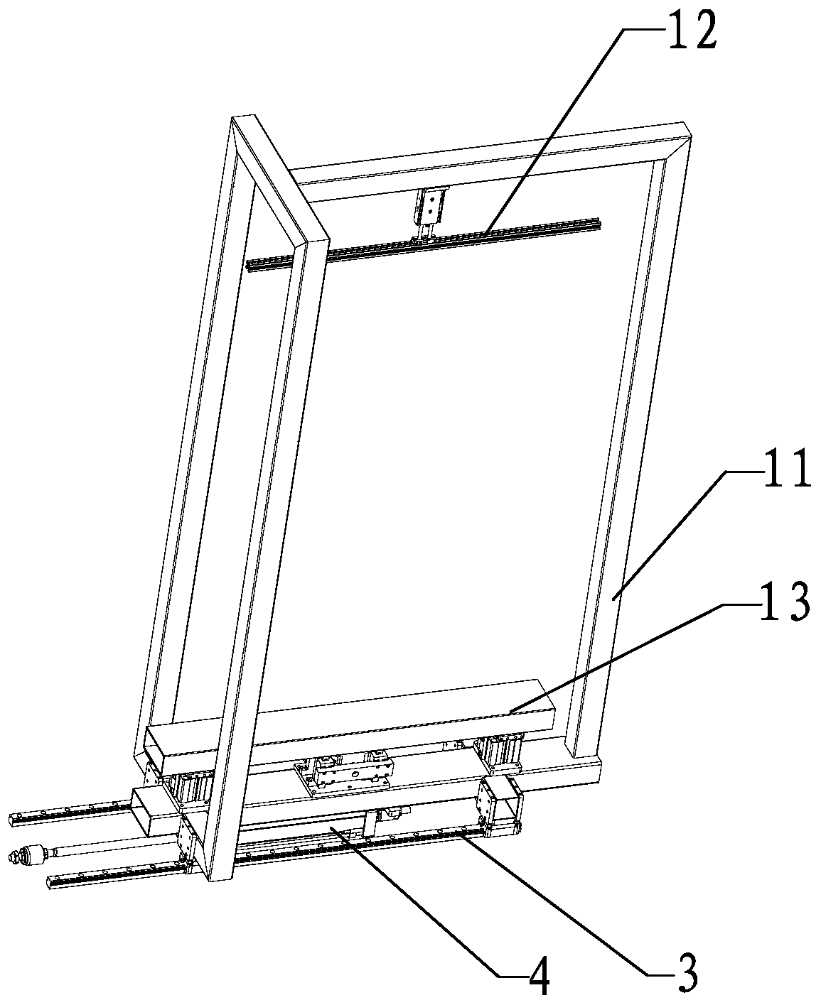
[0037] The first clamping mechanism 1 comprises an external support 11, and the upper and lower sides of the external support 11 are respectively provided with an upper clamping rod 12 and a lower clamping rod 13 driven by a cylinder, and the upper clamping rod 12 and the lower clamping rod 13 are arranged on the cylinder. Clamp the single-layer or double-...


PUM


Abstract

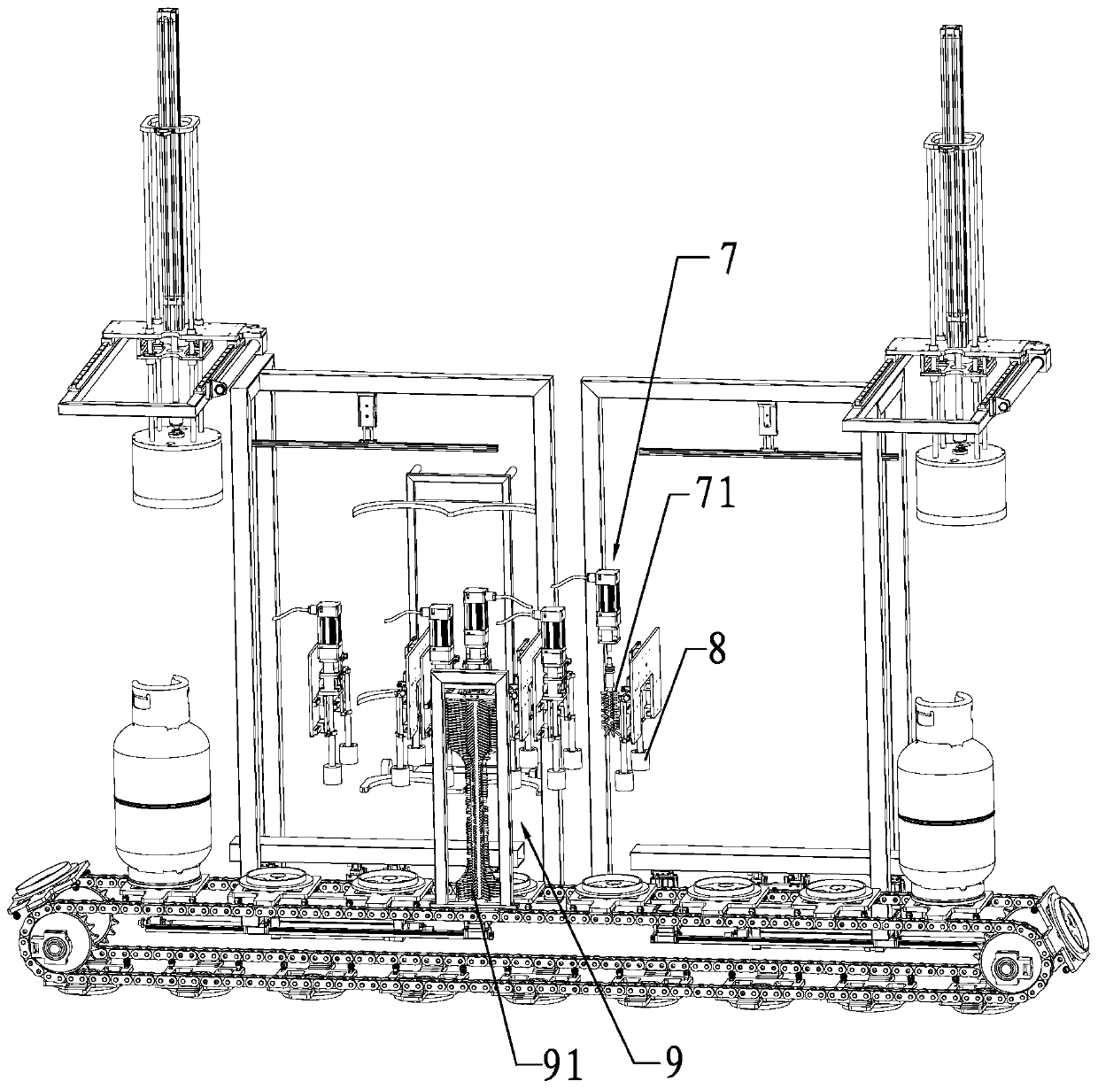
The invention relates to the field of cleaning liquefied gas steel cylinders, specifically an automatic cleaning method for a liquefied gas steel cylinder. The automatic cleaning method for the liquefied gas steel cylinder comprises the following steps of: pushing the steel cylinder to a first clamping mechanism by a cart, withdrawing the cart, transferring the steel cylinder by the first clampingmechanism, then transferring the steel cylinder to a conveyor belt from the end of the first clamping mechanism by a manipulator, spraying cleaning liquid on the steel cylinder, brushing the steel cylinder by a cleaning mechanism, and finally moving the steel cylinder out of the conveyor belt. After adopting the above scheme, the automatic cleaning of liquefied gas cylinder is realized, and the automatic cleaning method provided by the invention has practical commercial application prospect.

Description

technical field [0001] The invention relates to the field of cleaning liquefied gas cylinders, in particular to an automatic cleaning method for liquefied gas cylinders. Background technique [0002] The liquefied gas cylinder is a kind of steel cylinder for storing liquefied gas. Since it is usually placed near the kitchen gas stove when in use, its surface is easily contaminated with various oils. If it is not cleaned in time, it will lead to accelerated corrosion of the liquefied gas cylinder, and it cannot be removed from the Judging the mark on the surface of the liquefied gas cylinder by the appearance will bring inconvenience to maintenance and bury safety problems. [0003] At present, most gas stations generally adopt manual cleaning. Due to the weight of the liquefied gas cylinder itself (general household steel cylinder weighs about 15 kilograms), manual cleaning is very time-consuming and laborious, and the efficiency is low; the existing prior patent CN204122428...

Claims


Application Information

Patent Timeline
IPC IPC(8): B08B9/30B08B9/36B08B9/44
Inventor 李永付李峥博
Owner 绍兴恒研机电科技有限公司
Learn More