Eureka AIR delivers breakthrough ideas for toughest innovation challenges, trusted by R&D personnel around the world.

Optical cable identification device and identification method

A technology for identifying devices and optical cables, applied in the field of optical fiber communication, can solve the problems that are prone to misjudgment, the factors of personnel experience are greatly affected, and the optical cable is time-consuming and laborious, and achieves the effect of improving accuracy and efficiency.

Active Publication Date: 2021-02-12
WUHAN OVLINK TECH
View PDF9 Cites 0 Cited by
  • Summary
  • Abstract
  • Description
  • Claims
  • Application Information

AI Technical Summary

Problems solved by technology

[0009] There are certain defects in these methods. Pulling the optical cable is not only time-consuming and labor-intensive, but also inefficient, and it is easy to cause damage to the optical cable. Bending and freezing the optical cable are also easy to cause damage to the optical cable.
The identification is based on the principle of optical fiber sensing. Although the method is relatively novel, the identification of optical cables depends on human judgment whether there is a knock signal. When there is a certain amount of vibration interference, it is easy to misjudgment

Method used


Image

  • Optical cable identification device and identification method
  • Optical cable identification device and identification method
  • Optical cable identification device and identification method

Examples


Embodiment Construction

[0029] In order to facilitate the understanding of the present invention, the present invention will be described more fully below with reference to the associated drawings. Preferred embodiments of the invention are shown in the accompanying drawings. However, the present invention can be embodied in many different forms and is not limited to the embodiments described herein. On the contrary, these embodiments are provided to make the understanding of the disclosure of the present invention more thorough and comprehensive.

[0030] It should be noted that when an element is referred to as being “fixed” to another element, it can be directly on the other element or there can also be an intervening element. When an element is referred to as being "connected to" another element, it can be directly connected to the other element or intervening elements may also be present.

[0031] Unless otherwise defined, all technical and scientific terms used herein have the same meaning as...


PUM


Abstract

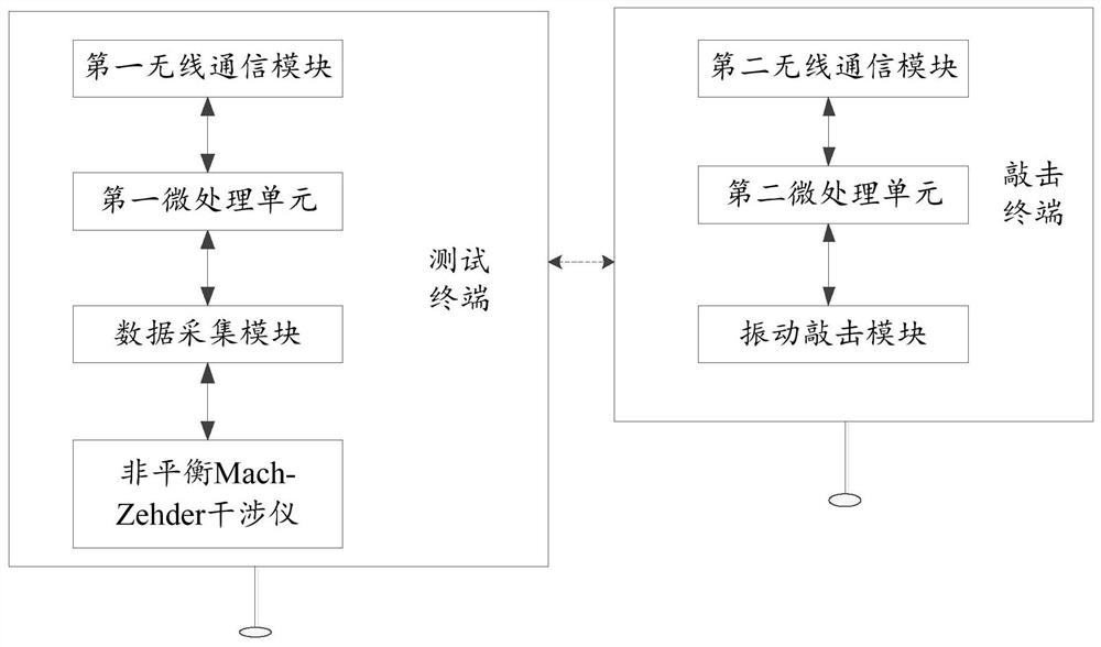
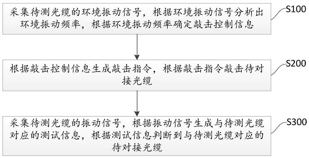
The invention relates to an optical cable identification device, comprising a test terminal and a knocking terminal; the test terminal comprises a first wireless communication module, a first micro control unit and an unbalanced Mach-Zehder interferometer; the unbalanced Mach-Zehder interferometer The instrument is used to convert the vibration signal collected from the optical cable to be tested into an electrical signal, the first micro-control unit is used to process the electrical signal and generate knocking control information and test information according to the electrical signal, the first The wireless communication module is used to transmit tapping control information and matching result information; the tapping terminal includes a second wireless communication module, a second micro control unit and a vibration tapping module. The present invention is based on optical fiber interference vibration sensing technology, adopts a vibration generator, and combines wireless communication technology to realize precise tapping on optical cables and accurate identification of tapping frequency, build a synchronous feedback mechanism, effectively select frequencies, and avoid interference frequency bands. The accuracy and efficiency of optical cable identification are improved.

Description

technical field [0001] The invention relates to the technical field of optical fiber communication, in particular to an optical cable identification device and identification method. Background technique [0002] The rapid development of optical fiber communication promotes the laying of more and more optical cables, and the maintenance of a huge number of optical cables has become a huge problem, especially with the continuous acceleration of urbanization and the rapid upgrading of urban infrastructure, engineering construction often leads to The damage and loss of the optical cable label may even cause the destruction of the optical cable. [0003] In the process of optical cable repair and optical cable resource census and statistics, it is often necessary to accurately find and identify target optical cables laid in pipelines (man wells), tunnels, overhead poles and other environments. Quickly finding target optical cables not only helps to reduce construction difficulty...

Claims


Application Information

Patent Timeline
Patent Type & Authority Patents(China)
IPC IPC(8): G01M11/00G01N29/04G01H9/00
Inventor 李晓磊王进王兵华
Owner WUHAN OVLINK TECH
Why Eureka
Eureka Blog
Learn More