Automatic knocking device and method for nondestructive testing

A non-destructive testing and automatic technology, applied in measurement devices, analysis of solids using sonic/ultrasonic/infrasonic waves, generation of ultrasonic/sonic/infrasonic waves, etc., can solve problems affecting the accuracy of evaluation results and other issues

Pending Publication Date: 2021-11-16
SHANGHAI CONSTRUCTION GROUP
View PDF8 Cites 0 Cited by
  • Summary
  • Abstract
  • Description
  • Claims
  • Application Information

AI Technical Summary

Problems solved by technology

[0004] Aiming at the problem that the existing non-destructive testing technology is difficult to truly reflect the internal structure of the tested wood, which seriously affects the accuracy of the evaluation results

Method used


Image

  • Automatic knocking device and method for nondestructive testing
  • Automatic knocking device and method for nondestructive testing
  • Automatic knocking device and method for nondestructive testing

Examples


Embodiment 1

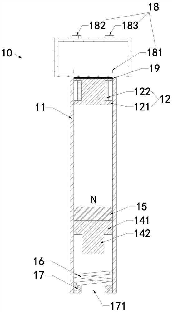
[0036] combine figure 1 with figure 2 Illustrate the non-destructive testing automatic knocking device 10 of the present invention, it comprises:

[0037]A cylindrical frame 11, which is a hollow cylindrical shell with one end closed, one end of the cylindrical frame 11 close to the detected object (not shown in the figure) is an open end, and the other end is provided with a closed end plate;

[0038] The electromagnet 12 is arranged in the inner cavity of the cylindrical frame 11 and fixed at one end close to the end plate;

[0039] The knocking assembly is arranged in the inner cavity of the cylindrical frame 11 and can slide along its axis. It includes a hammer head 141 and a magnetic block 15 arranged and connected in sequence along the axial direction. The hammer head 141 and the magnetic block 15 are connected to the cylindrical frame 11. The inner chamber of the magnetic block 15 is arranged opposite to the electromagnet 12 and fixedly connected to one end of the ha...

Embodiment 2

[0056] combine Figure 3 to Figure 6 Illustrate the non-destructive testing automatic tapping method of the present invention, concrete steps are as follows:

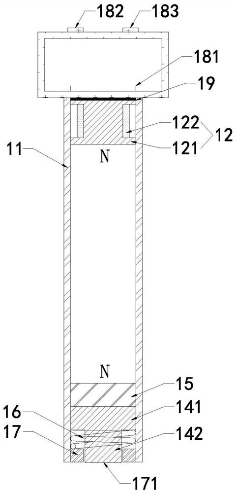
[0057] S1: Place the stress wave sensor on the top of the object to be detected and determine the knocking point, and vertically set the automatic knocking device 10 for non-destructive testing described in Embodiment 1 on the top of the knocking point, so that the hammer head 141 of the knocking assembly is quasi-tap point;

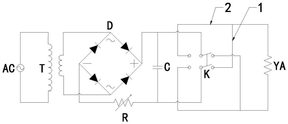
[0058] S2: if image 3 with Figure 4 As shown, adjust the control switch 182 of the main controller 18 to "off", the electromagnet 12 is non-magnetic, and the percussion assembly is attracted to the electromagnet 12 due to the magnetism of the magnet block 15 itself, and the control switch 182 is adjusted to "percussion". ”, the output terminal and input terminal of the double-pole double-throw switch in the control circuit are respectively connected to the interface of the first branch circui...


PUM


Abstract

The invention discloses an automatic knocking device and method for nondestructive testing, and relates to the technical field of nondestructive testing. The problem that an existing nondestructive testing technology is inaccurate in evaluation result is solved. The device comprises a barrel-shaped frame, an electromagnet and a knocking assembly which are arranged in an inner cavity of the barrel-shaped frame, and a main controller which is connected with the electromagnet, wherein the electromagnet is fixed to the closed end of the barrel-shaped frame, a hammer head and a magnetic block of the knocking assembly can slide along the axis of the barrel-shaped frame, the magnetic block is fixedly connected to one end of the hammer head, and the other end of the hammer head can be in contact with a detected object positioned at the open end of the cylindrical frame. The method comprises the following steps: aligning the hammerhead of the automatic knocking device for nondestructive testing to a knocking point, adjusting the magnetic pole of the electromagnet by using the control circuit, generating repulsive force when the magnetic poles of the electromagnet and the magnetic block are the same, sliding the knocking assembly towards a detected object and knocking, and generating suction force when the magnetic poles of the electromagnet and the magnetic block are opposite, wherein the knocking assembly slides towards the direction of the electromagnet and is attached to the electromagnet for resetting, so that different detected objects are knocked and detected repeatedly.

Description

technical field [0001] The invention relates to the technical field of nondestructive testing, in particular to an automatic tapping device and method for nondestructive testing. Background technique [0002] At present, the non-destructive testing technology based on the principle of stress wave is more and more widely used in wooden structure testing. Wooden structure testing can be divided into material performance testing, material defect testing, dimensional deviation and deformation testing, joint quality and structural performance testing, etc. , Non-destructive testing technology has the advantages of safety, simple operation, easy to carry, and suitable for on-site operations. [0003] During detection, the operator holds a small hammer and taps the contact of the stress wave sensor suspended on the wood to be detected, thereby stimulating the propagation of the stress wave. The stress wave sensor picks up the signal, and according to the wave theory, the propagatio...

Claims


Application Information

Patent Timeline
Patent Type & Authority Applications(China)
IPC IPC(8): G01N29/04G01N29/34
CPCG01N29/045G01N29/34
Inventor 尹婷婷韩振华
Owner SHANGHAI CONSTRUCTION GROUP
Why Eureka
Try Eureka