Large-view-field receiving device and large-view-field receiving method

A receiving device and a large field of view technology, applied in the optical field, can solve the problems of dark current and system noise that cannot be suppressed, large interference of detector performance, and difficult implementation, etc., and achieve the effects of easy implementation, signal interference resolution, and good stability

Pending Publication Date: 2019-05-28
BEIJING WANJI TECH
View PDF0 Cites 0 Cited by
  • Summary
  • Abstract
  • Description
  • Claims
  • Application Information

AI Technical Summary

Problems solved by technology

[0003] However, the current technical solution for receiving a large field of view often adopts a customized photodetector with a large photosensitive surface. With the increase of the photosensitive surface, its cost is expensive, and the overall performance of the detector is greatly disturbed by external ambient light, and its own dark current and System noise cannot be suppressed; there are also technical solutions to achieve large field of view reception by using complex optical lens group design, but the system is complex and difficult to implement

Method used


Image

  • Large-view-field receiving device and large-view-field receiving method
  • Large-view-field receiving device and large-view-field receiving method
  • Large-view-field receiving device and large-view-field receiving method

Examples


Embodiment Construction

[0041] The specific implementation manners of the present invention will be further described in detail below in conjunction with the accompanying drawings and embodiments. The following examples are used to illustrate the present invention, but are not intended to limit the scope of the present invention.

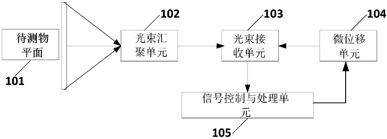
[0042] figure 1 It is a schematic structural diagram of a large field of view receiving device according to an embodiment of the present invention.

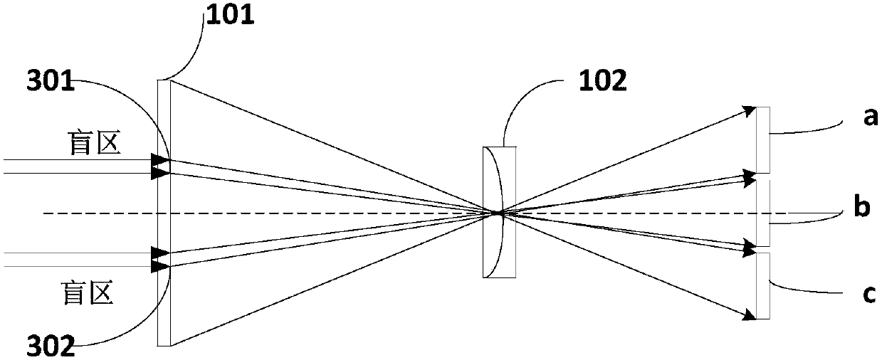
[0043] like figure 1 The large field of view receiving device shown includes: a beam converging unit 102 and a beam receiving unit 103; the beam converging unit 102 is used to receive the diffuse reflection beam of the object plane 101; the beam receiving unit 103 includes At least two photodetectors are arranged in a preset manner, the photosensitive surface of the photodetector is set corresponding to the beam converging unit 102, and is used to detect the optical signal transmitted by the beam converging unit 102 through...


PUM


Abstract

The invention provides a large-view-field receiving device and method. The device comprises a light beam gathering unit and a light beam receiving unit; the light beam gathering unit receives diffusereflection light beams of a plane of a to-be-detected object, and the diffuse reflection light beams are converged and then transmitted to the light beam receiving unit; the light beam receiving unitcomprises at least two photoelectric detectors which are arranged in a preset mode; the photosensitive surfaces of the photoelectric detectors are arranged corresponding to the light beam gathering unit. The light beam receiving unit detects an optical signal transmitted from the light beam gathering unit through the photosensitive surfaces of the at least two photoelectric detectors, and sub-view-field receiving is achieved. The at least two photoelectric detectors are adopted as the light beam receiving unit to achieve sub-view-field receiving so that large-view-field receiving can be achieved under the condition that the size of the photosensitive surface of a single photoelectric detector is not increased, more details of the plane of the to-be-detected can be obtained, the stability is good, the anti-interference performance is high, and the problems of signal interference of a customized photoelectric detector and the like are solved; a receiving optical system is simplified, thecost is reduced, and the method is easy to implement.

Description

technical field [0001] The present invention relates to the field of optics, and more specifically, to a large field of view receiving device and a large field of view receiving method. Background technique [0002] With the development of social science and technology, lidar technology has been widely used in various fields of society. Especially in recent years, unmanned driving has become one of the most anticipated automotive industries in the future. Lidar technology, as the key technology of driverless cars, has become the most effective solution for driverless environment sensing. When using lidar for detection, it is necessary to emit multiple beams of light to scan the field of view of the object to be measured to obtain information about the object to be measured. In order to obtain more detailed information of the object under test, it is often necessary to continuously increase the scanning angle and the line beam, and the corresponding receiving end needs to r...

Claims


Application Information

Patent Timeline
IPC IPC(8): G01S7/486G01S7/491G01S7/481
Inventor 陈佳屈志巍李军建张正正佟建
Owner BEIJING WANJI TECH
Why Eureka
Try Eureka