Coil component

一种线圈部件、芯部的技术,应用在变压器/电感的零部件、电气元件、电感器等方向,能够解决磁阻增加、粘合强度降低、不易兼顾粘合强度的确保和电感的确保等问题

Active Publication Date: 2019-05-28
MURATA MFG CO LTD
View PDF14 Cites 0 Cited by
  • Summary
  • Abstract
  • Description
  • Claims
  • Application Information

AI Technical Summary

Problems solved by technology

Moreover, it is undeniable that such a reduction in the bonding area will result in a reduction in the bonding strength between the top surface 6 of the flange portion 2 and the lower main surface 7 of the plate-shaped core portion 3.
In particular, if the coil component is miniaturized, for example, if the planar size is 0.4 mm x 0.2 mm or 0.2 mm x 0.1 mm, which is less than 1 mm, the reduction of the bonding area will have a profound impact on the reduction of the bonding strength. influences
As mentioned above, if the area of ​​the inclined surfaces 12 and 13 is enlarged, the magnetic resistance increases, and as a result, the inductance of the coil component decreases.
[0012] Due to this situation, it is difficult to achieve both the securing of the adhesive strength and the securing of the inductance

Method used


Image

  • Coil component
  • Coil component
  • Coil component

Examples


Embodiment Construction

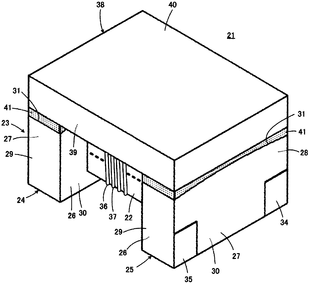
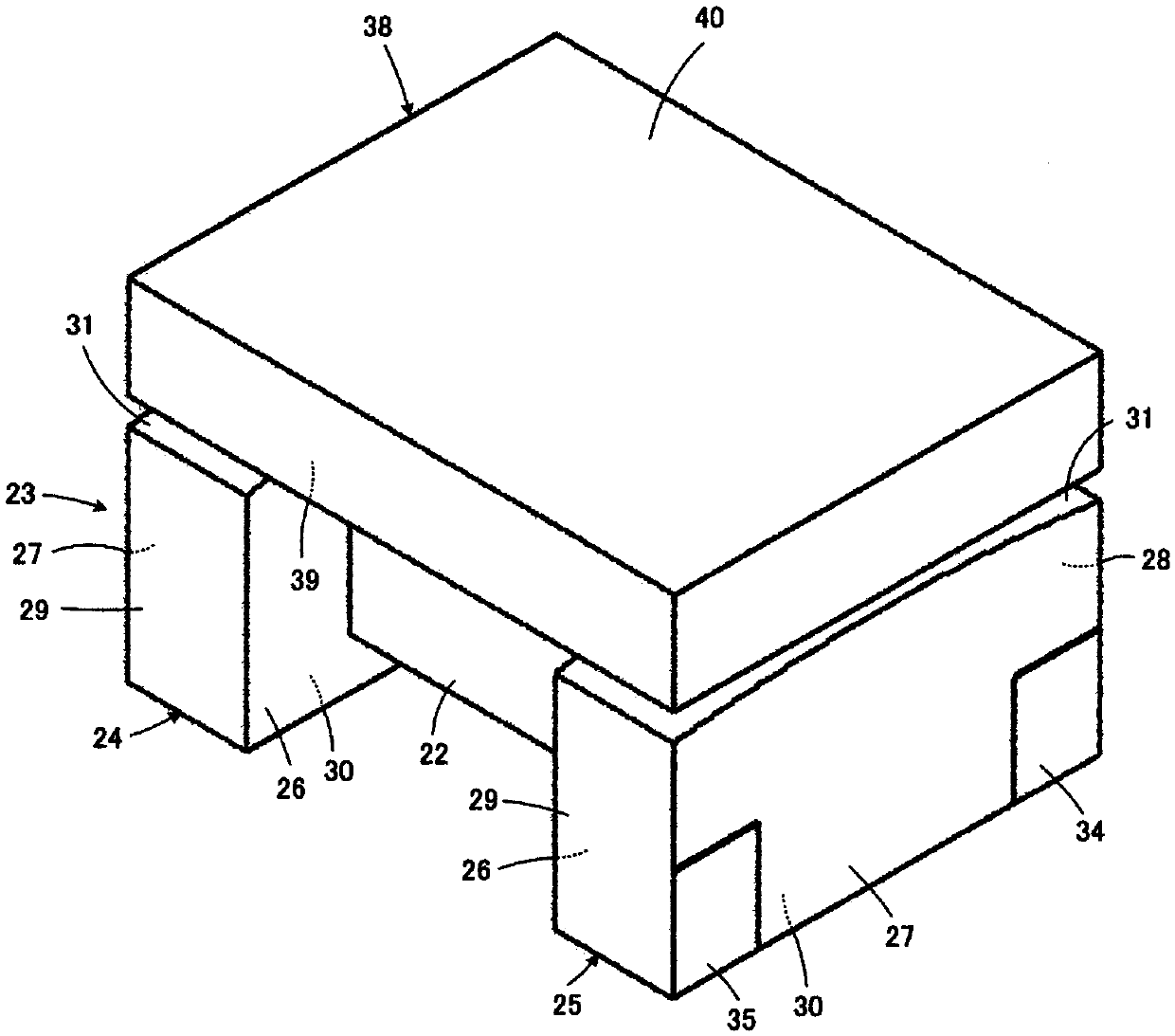
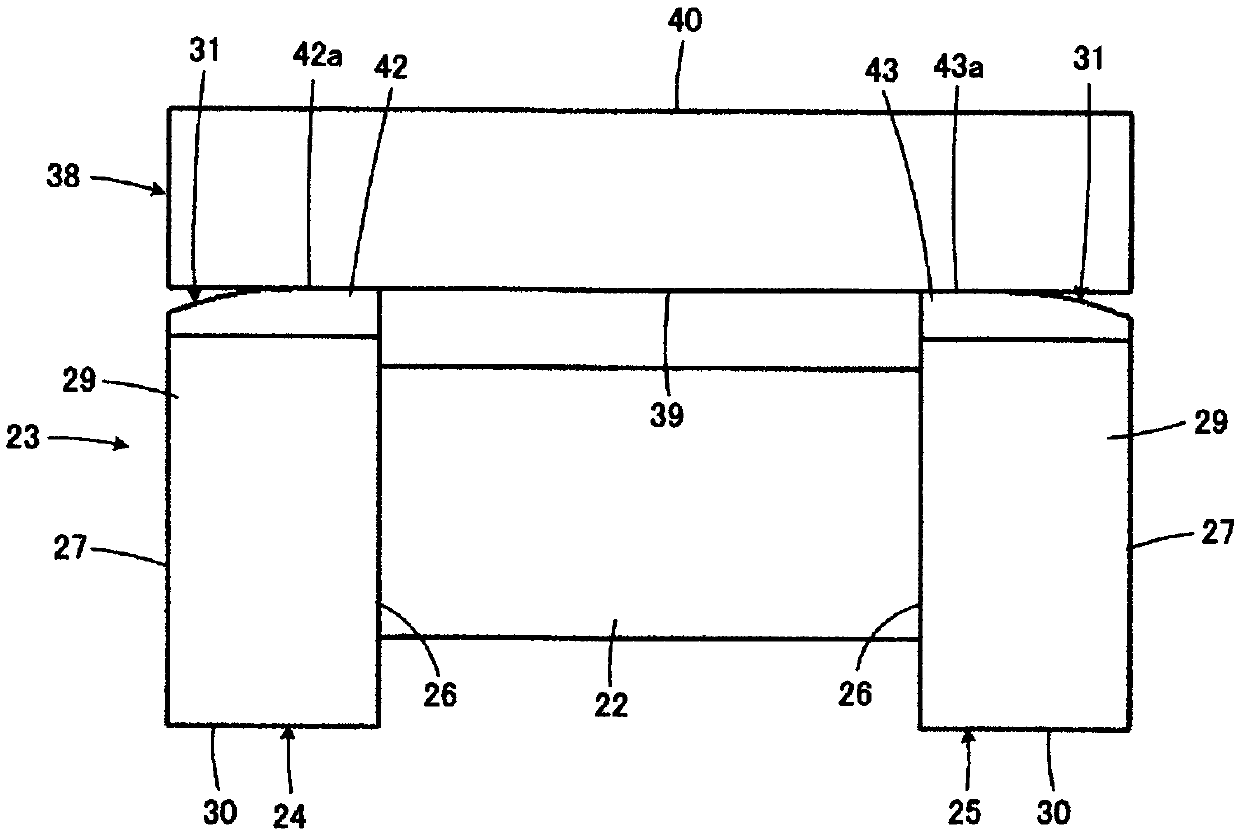
[0044] refer to Figure 1 ~ Figure 4 , the coil component 21 according to the first embodiment of the present invention will be described. The illustrated coil component 21 constitutes, for example, a common mode choke coil.

[0045] The coil component 21 includes a drum-shaped core 23 having a winding core 22 . The drum-shaped core portion 23 is provided with a first flange portion 24 and a second flange portion 25 respectively provided at first and second end portions opposite to each other in the axial direction of the winding core portion 22 . The drum-shaped core 23 is made of a magnetic material, more specifically, a magnetic body such as NiZn ferrite, a resin containing a metal amorphous material or magnetic powder, or the like. The winding core portion 22 included in the drum-shaped core portion 23 has, for example, a quadrangular prism shape having a substantially quadrangular cross-sectional shape.

[0046] The first flange portion 24 and the second flange portion...


PUM


Abstract

The present invention provides a coil component having a structure in which the adhesive strength of an adhesive portion between a drum core portion and a plate-like core portion is secured to a predetermined value or more and the inductance can be suppressed. A coil component includes a drum core including a winding core portion and a flange portion disposed on an end portion thereof the windingcore portion in its axial direction, a planar core having a lower principal surface, and a wire wound around the winding core portion. The flange portion includes an inner end surface, an outer end surface, a bottom surface, and a top surface. The inner end surface positions the end portion of the winding core portion. The bottom surface links the inner end surface and the outer end surface and placed so as to face a mounting substrate side when being mounted. The lower principal surface of the planar core is fixed to the top surface with an adhesive interposed therebetween. The top surface includes a protrusion with a vertex positioned closer to the inner end surface than to the outer end surface.

Description

technical field [0001] The present disclosure relates to a coil component, and particularly relates to a coil component including a drum-shaped core and a plate-shaped core. Background technique [0002] As the prior art, there is, for example, the technology described in Japanese Patent No. 5796603 (Patent Document 1). Figure 14 is based on Patent Document 1 figure 2 (a), one flange portion 2 and the plate-shaped core portion 3 of the drum-shaped core portion 1 of the coil component are shown in the figure. [0003] The drum-shaped core 1 has a winding core around which a wire rod is wound, and first and second flanges respectively provided at respective ends of the winding core. Figure 14 In the drawing, one flange portion 2 of the first flange portion and the second flange portion is shown. The flange part 2 has: an inner end surface (not shown) facing the core part side and positioning each end of the core part; The bottom surface 5 facing the side of the mounting s...

Claims


Application Information

Patent Timeline
Patent Type & Authority Applications(China)
IPC IPC(8): H01F17/04
CPCH01F17/045H01F27/263H01F27/38H01F27/24H01F27/2823
Inventor 五十岚启雄五十岚勇治桥本贤治
Owner MURATA MFG CO LTD
Why Eureka
Try Eureka