
Battery

A battery and battery cell technology, applied in battery pack parts, battery boxes/jackets, circuits, etc., can solve the problems of not being a commodity, detachment, economic loss, etc., to prevent detachment, ensure the bonding area, and improve the yield. Effect

Inactive Publication Date: 2003-01-22
KYOCERA CORP
View PDF0 Cites 0 Cited by
  • Summary
  • Abstract
  • Description
  • Claims
  • Application Information

AI Technical Summary

Problems solved by technology

[0009] However, in the above-mentioned battery, when the battery unit 1 is molded, there is a part of the joint strength between the battery unit 1 and the molded part 2 that is insufficient in bonding strength. The problem that a part of the battery is separated from the battery cell 1
[0010] That is, in the above-mentioned battery, since the electrode terminal 10 such as the lead-out portion 15 of the electrode terminal 10 is in contact with the side surface 4, etc., is located at a position close to the side surfaces 4, 11 of the battery cell 1, resin cannot flow into the electrode terminal during molding. 10 and the sides 4, 11, therefore, for the sides 4, 11 of this part, the combined area of ​​the molded part 2 is insufficient, resulting in insufficient bonding strength of this part, resulting in the molded part 2 Figure 4 The part shown in the symbol 20 forms a problem of detachment
[0011] Moreover, in the above-mentioned battery, if the molded part 2 is detached from the battery unit 1, it cannot be provided to the market as a commodity, and it is not easy to disassemble and reuse from the perspective of cost balance, thus causing battery damage. Low manufacturing yield, resulting in huge economic losses

Method used


Image

  • Battery
  • Battery
  • Battery

Examples


Embodiment Construction

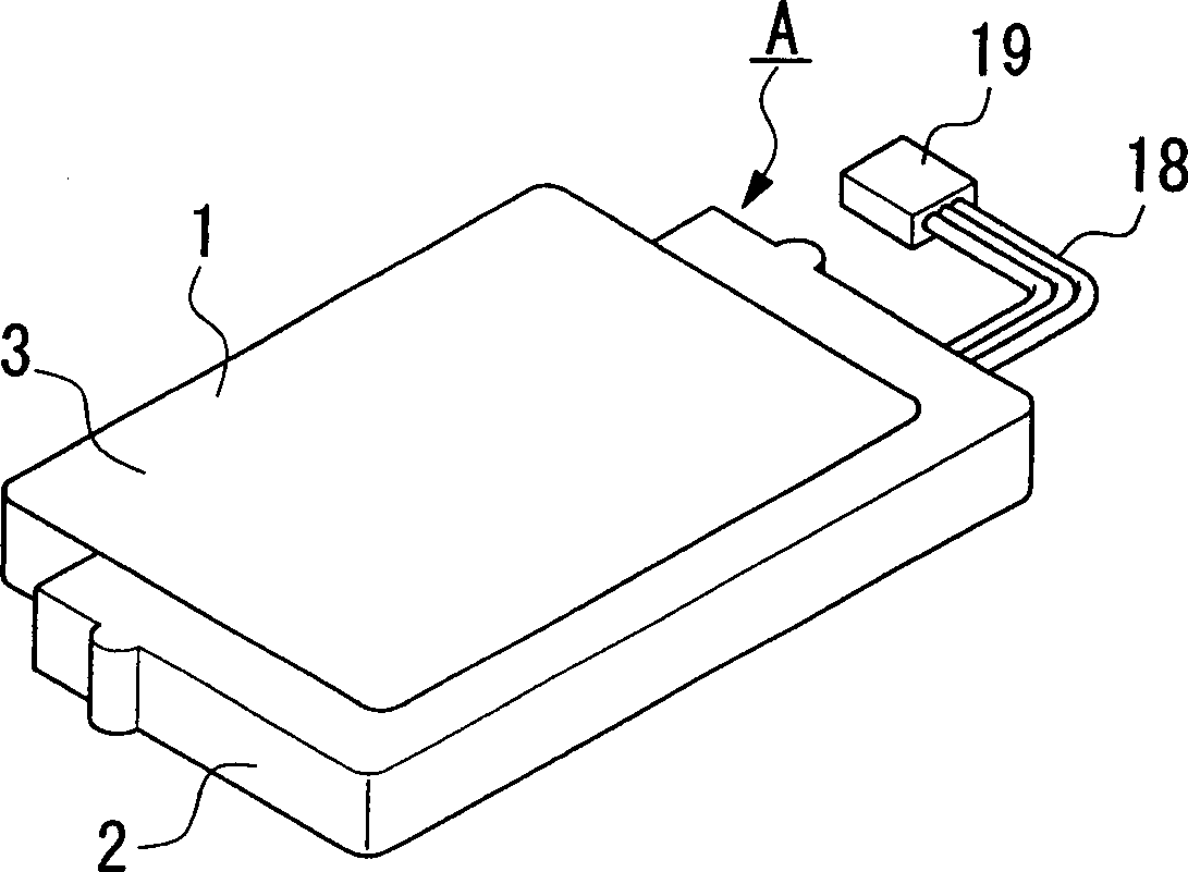
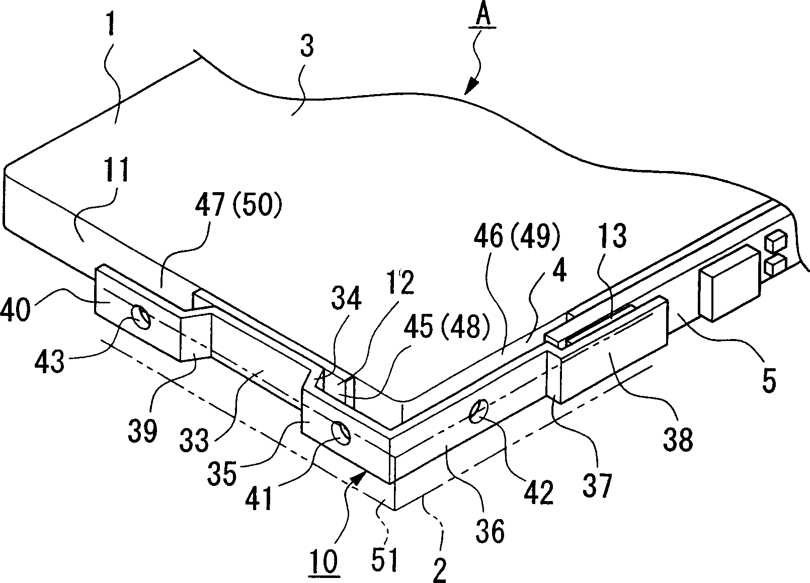
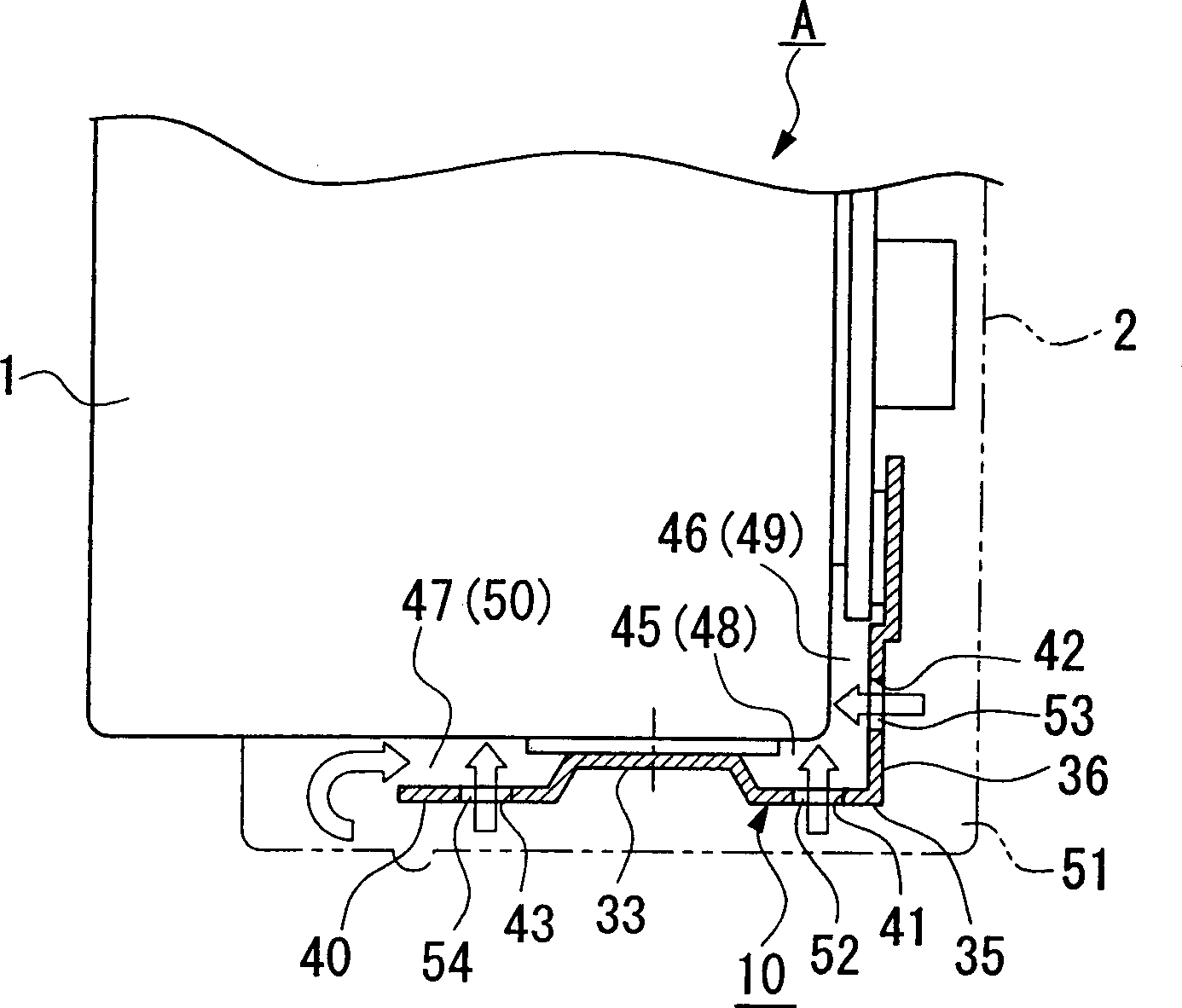
[0029] Hereinafter, an embodiment of the present invention will be described with reference to the accompanying drawings. Figure 1 to Figure 3 Indicates that the mobile terminal battery of the present invention is applied, and the mobile terminal battery A (battery) shown in the figure includes a battery unit 1, a circuit board 5 assembled in the battery unit 1, and the battery unit 1 and the circuit board 5. The electrode terminals 10 for circuit connection are formed, and the circuit board 5 and the electrode terminals 10 are integrated with the battery cell 1 through the molding part 2. This basic structure is related to the Figure 4 to Figure 6 The cells shown are of the same construction.

[0030] In addition, in Figure 1 to Figure 3 , for which and Figure 4 to Figure 6 The parts shown with the same configuration use the same symbols, and their descriptions are omitted. Below, only for Figure 4 to Figure 6 different parts are explained.

[0031] The battery A for m...


PUM


Abstract

In order to provide a battery in which a molded section can be fixed to a battery cell, a battery comprises a battery cell, a circuit board which is attached to the battery cell, an electrode terminal which connects the battery cell and the circuit board electrically, a molded section which adheres the circuit board and the electrode terminal to the battery cell as an entire unit, adhesion strengthened areas which are formed between the electrode terminal and the battery, and electrode terminal inner surface resin sections which are formed in a part of the molded section of the adhesion strengthened area.

Description

technical field [0001] The present invention relates to batteries used in mobile terminals and the like, and particularly to batteries having circuit boards. Background technique [0002] As a battery conventionally used in a mobile terminal such as a mobile phone, there is provided a battery in which various circuit boards such as an overcurrent protection circuit board are arranged in a battery unit. In general, the above-mentioned circuit board is encapsulated in the battery unit by molding resin for the convenience of use and neat appearance of the battery. [0003] Figure 4 to Figure 6 An example of the above-mentioned conventional battery is shown, and the Figure 4 In the figure, reference numeral 1 denotes a battery cell, and reference numeral 2 denotes a die-formed part. The battery cell 1 has a rectangular shape with a certain thickness, and the entirety of the battery cell 1 is substantially covered by an aluminum casing 3 , the casing 3 constitutes a positive ...

Claims


Application Information

Patent Timeline
Patent Type & Authority Applications(China)
IPC IPC(8): B65D85/00H01M10/42H01M50/103H01M50/528H01M50/529H01M50/553H01M50/564
CPCH01M2/30Y02E60/12H01M10/42H01M2/0207H01M10/425Y02E60/10H01M50/564H01M50/103H01M50/553
Inventor 山崎真人
Owner KYOCERA CORP
Learn More