

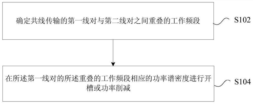
Collinear transmission method and device
A transmission method and collinear technology, applied in line transmission components, line fault/interference reduction, baseband system components, etc., can solve problems such as crosstalk between adjacent lines, and achieve the effect of optimizing transmission performance
- Summary
- Abstract
- Description
- Claims
- Application Information
AI Technical Summary
Problems solved by technology
Method used
Image

Examples
Embodiment 1
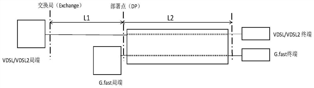
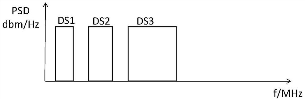
[0048] Such as figure 2 As shown, this embodiment is aimed at the scenario where VDSL / VDSL2 and G.fast coexist, wherein VDSL / VDSL2 adopts the FDD mode, and its downlink spectrum is as follows image 3 As shown, the spectrum in the uplink direction is shown as Figure 4 shown. G.fast spectrum such as Figure 5 shown. The specific steps of the solution provided in this embodiment are as follows:
[0049] 1. Obtain the transmission mode of the adjacent line pair of the G.fast line, the working frequency band overlapping with the G.fast own line pair, the overlapping frequency band in the downlink direction and the overlapping frequency band in the uplink direction, and determine the opening in order to avoid near-end crosstalk (NEXT). Which overlapping frequency bands are notched; and determine the PSD (power spectral density) of adjacent lines at the deployment point in the unnotched working frequency band.
[0050] (1) Since VDSL / VDSL2 (collectively referred to as VD) ado...
Embodiment 2
[0086] Such as figure 2 As shown, this embodiment is aimed at the scenario where VDSL / VDSL2 and G.fast coexist, wherein VDSL / VDSL2 adopts the FDD mode, and its downlink spectrum is as follows image 3 As shown, the spectrum in the uplink direction is shown as Figure 4 shown. G.fast spectrum such as Figure 5 shown. The specific steps of the solution provided in this embodiment are as follows:
[0087] 1. Obtain the transmission mode of the adjacent line pair of the G.fast line, the working frequency band overlapping with the G.fast line pair, the overlapping frequency band in the downlink direction and the overlapping frequency band in the uplink direction, and determine Notching in order to avoid near-end crosstalk (NEXT) Which overlapping frequency bands to drop; and determine the PSD (power spectral density) of adjacent lines at the deployment point in the working frequency band that has not been notched.
[0088] (1) Since VDSL / VDSL2 (collectively referred to as VD)...
Embodiment 3
[0125] Such as figure 2 As shown, this embodiment is aimed at the scenario where VDSL / VDSL2 and G.fast coexist, wherein VDSL / VDSL2 adopts the FDD mode, and its downlink spectrum is as follows image 3 As shown, the spectrum in the uplink direction is shown as Figure 4 shown. G.fast spectrum such as Figure 5 shown. The specific steps of the solution provided in this embodiment are as follows:
[0126] 1. Obtain the transmission mode of the adjacent line pair of the G.fast line, the working frequency band overlapping with the G.fast line pair, the overlapping frequency band in the downlink direction and the overlapping frequency band in the uplink direction, and determine Notching in order to avoid near-end crosstalk (NEXT) Which overlapping frequency bands to drop; and determine the PSD (power spectral density) of adjacent lines at the deployment point in the working frequency band that has not been notched.
[0127] (1) Since VDSL / VDSL2 (collectively referred to as VD)...
PUM
 Abstract
Description
Claims
Application Information