
Lasers for curved surface marking

A laser and curved surface technology, applied in the field of marking lasers, can solve the problems of difficult clamping of curved surface objects, low marking efficiency, troublesome operation, etc., and achieve the effect of enhancing applicability and facilitating vertical clamping

Active Publication Date: 2021-10-08
合肥齐泰光电科技有限公司
View PDF8 Cites 0 Cited by
  • Summary
  • Abstract
  • Description
  • Claims
  • Application Information

AI Technical Summary

Problems solved by technology

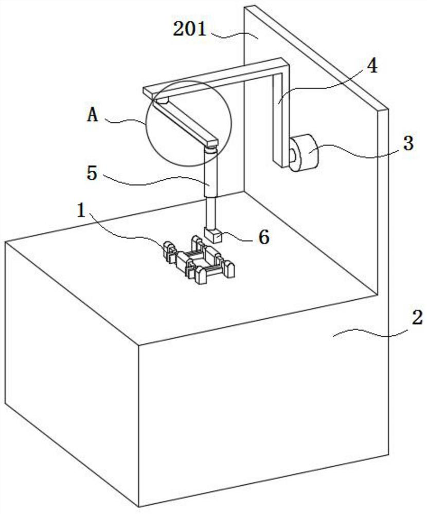
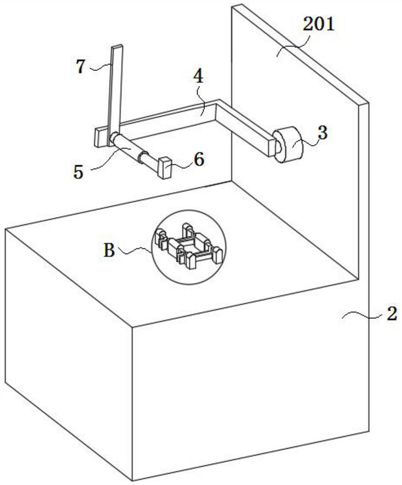
[0003] At present, when the existing marking lasers mark the arc-surface objects, they usually use the rotating fixture to clamp the arc-surface objects and then perform the marking action, but some arc-surface objects are difficult to clamp, making the arc-surface objects There are many restrictions in the marking work, the operation is more troublesome, and the marking efficiency is low

Method used


Image

  • Lasers for curved surface marking
  • Lasers for curved surface marking
  • Lasers for curved surface marking

Examples


Embodiment Construction

[0024] The following will clearly and completely describe the technical solutions in the embodiments of the present invention with reference to the accompanying drawings in the embodiments of the present invention. Obviously, the described embodiments are only some, not all, embodiments of the present invention. Based on the embodiments of the present invention, all other embodiments obtained by persons of ordinary skill in the art without creative efforts fall within the protection scope of the present invention.

[0025] In the description of the present invention, it should be understood that the terms "opening", "upper", "middle", "length", "inner", etc. indicate orientation or positional relationship, and are only for the convenience of describing the present invention and simplifying the description , rather than indicating or implying that the components or elements referred to must have a particular orientation, be constructed and operate in a particular orientation, an...


PUM


Abstract

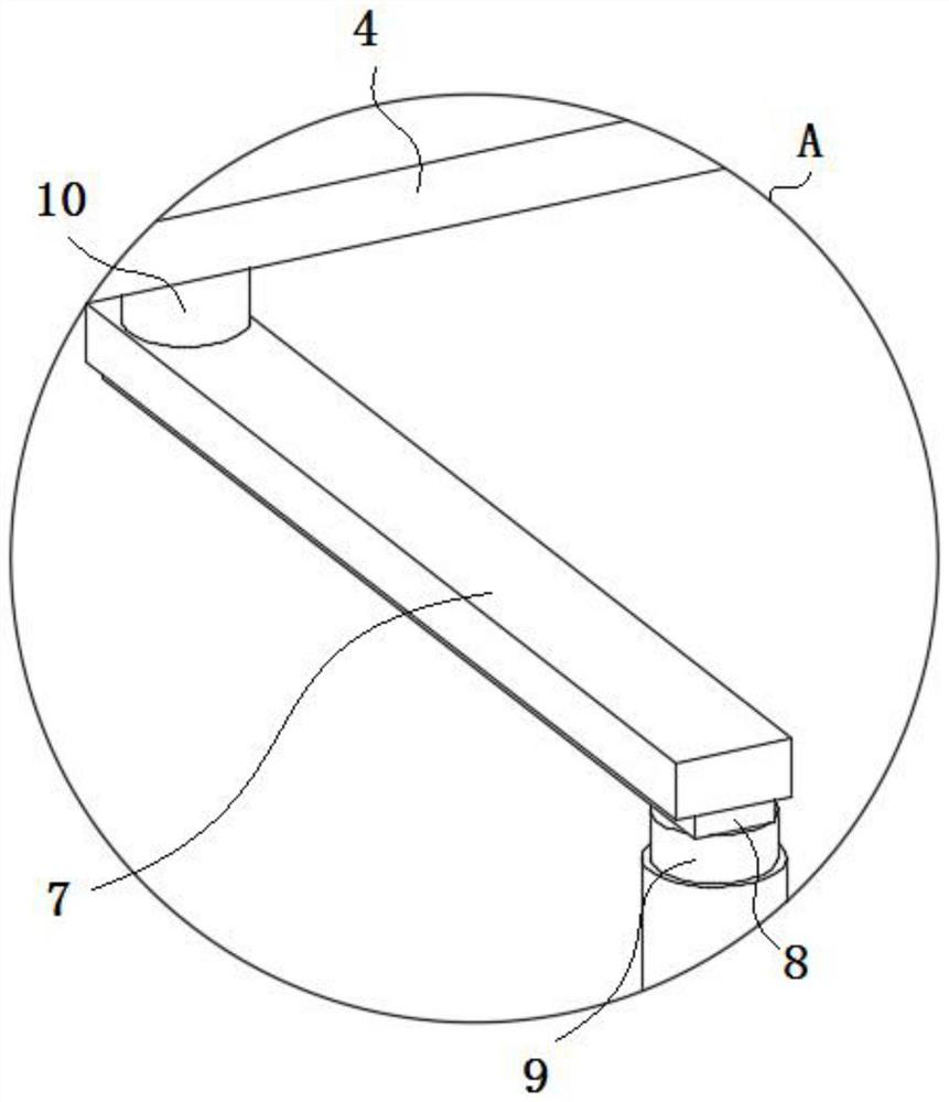
The invention discloses a laser used for arc surface marking, and relates to the technical field of marking lasers. The invention includes a cabinet, one side of the cabinet is provided with a side plate, a first motor is installed on the side plate, an output end of the first motor is fixed with a support rod, and the support rod is rotated through a fixed rod to cooperate with an electric push rod. A laser marking head is fixed at the output end; a clamping member is installed on the upper part of the cabinet, and the clamping member includes two symmetrically arranged clamping assemblies, a notch is formed on both sides of the clamping assembly, and a cavity is arranged in the clamping assembly. A shifting block is movably fitted in the cavity of the clamping component and located on both sides of the notch. The invention realizes the effect of marking the inner wall of the arc surface by fixing the laser marking head on the electric push rod, and rotating the electric push rod to match the electric push rod on the fixed rod. Vertical or horizontal clamping enhances its applicability, more versatility, and meets the needs of curved surface marking.

Description

technical field [0001] The invention belongs to the technical field of marking lasers, in particular to a laser used for marking arc surfaces. Background technique [0002] Marking lasers use laser beams to make permanent marks on the surface of various materials. The effect of marking is to expose the deep material through the evaporation of the surface material, so as to carve exquisite patterns, trademarks and characters. Laser marking machines are mainly divided into CO2 laser marking machines, semiconductor laser marking machines, and fiber laser marking machines. And YAG laser marking machine, laser marking machine is mainly used in some occasions that require finer and higher precision. Used in electronic components, integrated circuits (IC), electrical appliances, mobile communications, hardware products, tool accessories, precision instruments, glasses clocks, jewelry, auto parts, plastic buttons, building materials, PVC pipes. [0003] At present, when the existi...

Claims


Application Information

Patent Timeline
Patent Type & Authority Patents(China)
IPC IPC(8): B23K26/362B23K26/08B23K26/70
Inventor 王建国张前程王建民
Owner 合肥齐泰光电科技有限公司
Learn More