Automatic spanner and spanner fixture thereof

An automatic wrench and wrench technology, applied in the direction of wrenches, power tools, manufacturing tools, etc., can solve the problems of difficult operation and narrow adaptability, and achieve the effect of fast and convenient work, high work efficiency, and convenient clamping

Inactive Publication Date: 2019-05-31
北渤智能科技秦皇岛有限公司
View PDF1 Cites 12 Cited by
  • Summary
  • Abstract
  • Description
  • Claims
  • Application Information

AI Technical Summary

Problems solved by technology

[0005] Based on this, it is necessary to provide an automatic wrench and its wrench fixture with convenient clamping, simple operation and wide adaptability for the problem that the clamping process of the workpiece in the automatic wrench is complicated, difficult to operate, and the scope of application is narrow.

Method used


Image

  • Automatic spanner and spanner fixture thereof
  • Automatic spanner and spanner fixture thereof
  • Automatic spanner and spanner fixture thereof

Examples


Embodiment approach

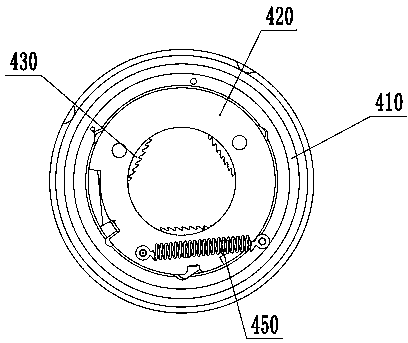
[0107] see Figure 3 to Figure 6 The first preferred embodiment of the shown wrench clamp of the present invention, the wrench clamp includes:

[0108] The outer ring 410 is a circular ring;

[0109] The inner ring 420 is a circular ring located inside the outer ring 410 and connected with the outer ring 410 by sliding or rolling;

[0110] Clamping jaws 430 are arranged in the inner ring 420, cooperate with the inner ring 420 and the outer ring 410 to clamp the workpiece; preferably, the clamping jaws 430 are wedge-shaped blocks, and the number of clamping jaws 430 is three and evenly distributed on the inner ring 420, the groove 4305 on each jaw 430 is slidingly matched with the support column 4201 on the inner ring 420; The supporting surface 4103 pushes the bearing surface 4301 on the jaws 430 to make the three jaws 430 move synchronously to the direction of clamping the workpiece to clamp the workpiece. The working surface where the jaws 430 contact with the workpiece is...

Embodiment 2

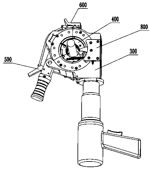
[0114] see Figure 7 to Figure 9 The second preferred embodiment of the shown wrench clamp of the present invention differs from the first preferred embodiment in that: the outer ring 410 and the inner ring 420 each include two parts; the main split support ring 421 is provided with The first stopper 440; the first stopper 440 cooperates with the positioning device 800 on the housing 300 to position the main cutting support ring 421 when it rotates in reverse;

[0115] The outer ring 410 includes:

[0116] main split worm gear 411; its sector angle is greater than or equal to 180°, and

[0117] Secondary splitting worm gear 412, whose fan angle is less than or equal to 180°; spliced ​​with main splitting worm gear 411 to form a whole;

[0118] The inner ring 420 includes:

[0119] The main splitting support ring 421, whose fan-shaped included angle is greater than or equal to 180°, is the same as the fan-shaped included angle of the main splitting worm wheel 411, and is loc...

Embodiment 3

[0126] see Figure 10 to Figure 12 The third preferred embodiment of the wrench clamp of the present invention shown is different from the second preferred embodiment in that: the jaw 430 is a swing block, the outer ring 410 has a slot 4123, and the inner ring 420 contains Support column 4201, jaw 430 includes:

[0127] The extension part 4304 is located in the slot 4123;

[0128] The teeth 4306 are arranged on the working surface where the jaw 430 contacts the workpiece;

[0129] The hole 4303 is provided on the clamping jaw 430 and is rotatably connected with the support column 4201 .

[0130] The wrench fixture of this embodiment clamps the workpiece through the swing of the swing block, which has high flexibility and sensitive response. The wrench fixture of this embodiment can also adapt to a wide range of working diameters, and does not need to be replaced every time for workpieces of different specifications. Gripper, high work efficiency, fast and convenient work. ...


PUM


Abstract

The invention discloses a spanner fixture. The spanner fixture comprises an outer ring, an inner ring, clamping jaws and a fifth elastic piece; the inner ring is positioned on the inner side of the outer ring, and is rotationally connected with the outer ring; the clamping jaw is matched with the inner ring and the outer ring to clamp workpieces; the fifth elastic piece is connected with the innerring and the outer ring; the outer ring is driven to rotate by external power; the fifth elastic piece generates acting force, so that the outer ring and the inner ring generate relative motion tendency; the tendency enables the outer ring to push the clamping jaws to synchronously move to a workpiece clamping direction to clamp the workpieces; and then, the inner ring is driven to rotate. The spanner fixture can adapt to wide-range working diameters, has no need to replace the clamping jaws every time for the workpieces with different specifications, achieves high working efficiency, and automatically aligns the workpieces in the clamping process to achieve the working speediness and convenience. Meanwhile, the invention provides an automatic spanner applying the spanner fixture.

Description

technical field [0001] The invention relates to the field of automatic tools, in particular to an automatic wrench and a wrench clamp thereof. Background technique [0002] Our company is committed to the research and development and production of electric tools. After investing a lot of research and development funds and labor costs and experiencing many research and development attempts and failures, we finally found out a practical, suitable for mass production and used for steel sleeve connection. Automatic wrench, after carrying this product through on-site visits and tests on construction sites in several provinces in China, it was found that steel workers on the construction site have great interest and demand for this automatic wrench. It is initially estimated that the domestic market has a market of over 100 million yuan, so the company decided to sell it It is mass-produced and put into market use. [0003] At present, when people need to connect and fasten steel...

Claims


Application Information

Patent Timeline
Patent Type & Authority Applications(China)
IPC IPC(8): B25B21/02B25B23/00B25B11/02
Inventor 杨新军宋竹校李圣元李清江李娜
Owner 北渤智能科技秦皇岛有限公司
Why Eureka
Try Eureka