
Plate type workpiece conveying equipment

A technology for conveying equipment and workpieces, which is applied in the field of plate-type workpiece conveying equipment, can solve the problems of reducing the working efficiency and service life of the power mechanism, increasing the output energy consumption of the power mechanism and working powerfully, and affecting the safety of equipment use, etc., and achieves exquisite structural design , Reduce the use of raw materials, improve the effect of safety

Active Publication Date: 2019-05-31
广东万合智能装备有限公司
View PDF10 Cites 1 Cited by
  • Summary
  • Abstract
  • Description
  • Claims
  • Application Information

AI Technical Summary

Problems solved by technology

[0002] Most of the existing furniture panel processing factories use horizontal conveying to transfer panels and perform panel flipping and stacking operations. Due to different panel processing techniques, the panels need to be three-dimensional before being transported, flipped, and stacked. Few of the factories The equipment can directly support and transport the heavy boards in the vertical direction, and then realize the functions of flipping and stacking the boards, because it is mainly reflected in two technical problems: 1. It is difficult for large boards to be erected Align the supporting station of the conveying equipment, causing the plate to seriously deviate when entering the supporting station, which affects the safety of the equipment; 2. The weight of the plate is heavy, and the structure of the supporting plate needs to have a strong support The capacity and structural strength will seriously increase the output energy consumption and strong work of the power mechanism on the transmission equipment that transmits the plate support structure, reducing the working efficiency and service life of the power mechanism

Method used


Image

  • Plate type workpiece conveying equipment
  • Plate type workpiece conveying equipment

Examples


Embodiment Construction

[0019] Embodiments of the present invention are described in detail below, examples of which are shown in the drawings, wherein the same or similar reference numerals denote the same or similar elements or elements having the same or similar functions throughout. The embodiments described below by referring to the figures are exemplary only for explaining the present invention and should not be construed as limiting the present invention.

[0020] In describing the present invention, it should be understood that the terms "center", "longitudinal", "transverse", "length", "width", "thickness", "upper", "lower", "front", " Orientation indicated by rear, left, right, vertical, horizontal, top, bottom, inside, outside, clockwise, counterclockwise, etc. The positional relationship is based on the orientation or positional relationship shown in the drawings, which is only for the convenience of describing the present invention and simplifying the description, rather than indicating ...


PUM


Abstract

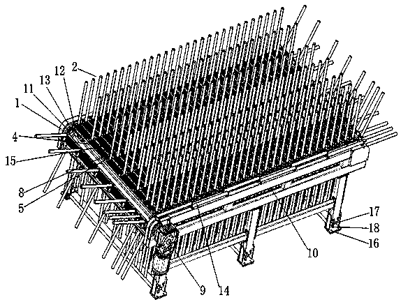
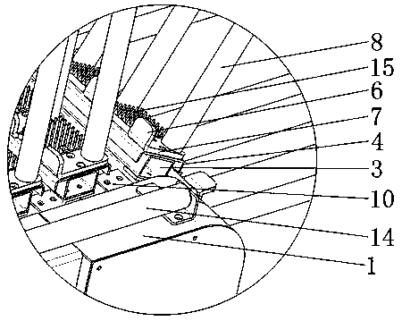
The invention provides plate type workpiece conveying equipment. The plate type workpiece conveying equipment comprises a rack, a conveying mechanism and a support frame mechanism, wherein a pluralityof carrier assemblies are arranged in the support frame mechanism, and distances between the adjacent two carrier assemblies sequentially increase in the feeding direction. A plate is fed in from theend, at which the carrier assemblies are densely distributed, of a mounting base, the densely arranged carrier assemblies play a guide function on the plate which is just fed in, the plate linearly moves, and the phenomenon that the plate cannot be supported by the carrier assemblies when the plate deviates in the process of moving away from other conveying equipment is prevented, so that the usesafety of the structure is improved. After the plate is guided, the number of the carrier assemblies used for the following conveying process of the plate can be reduced as long as installing distances between the adjacent two carrier assemblies at the upper part of the mounting base are increased to realize stable support on the two ends of the plate. The arrangement mode reduces the usage of raw materials, reduces the conveying pressure of a conveying mechanism and increases the conveying efficiency of the conveying mechanism.

Description

technical field [0001] The invention relates to the technical field of furniture board processing, in particular to a board-type workpiece conveying device. Background technique [0002] Most of the existing furniture panel processing factories use horizontal conveying to transfer panels and perform panel flipping and stacking operations. Due to different panel processing techniques, the panels need to be three-dimensional before being transported, flipped, and stacked. Few of the factories The equipment can directly support and transport the heavy boards in the vertical direction, and then realize the functions of flipping and stacking the boards, because it is mainly reflected in two technical problems: 1. It is difficult for large boards to be erected Align the supporting station of the conveying equipment, causing the plate to seriously deviate when entering the supporting station, which affects the safety of the equipment; 2. The weight of the plate is heavy, and the st...

Claims


Application Information

Patent Timeline
Patent Type & Authority Applications(China)
IPC IPC(8): B65G57/11B65G17/12
Inventor 程登高
Owner 广东万合智能装备有限公司
Learn More