

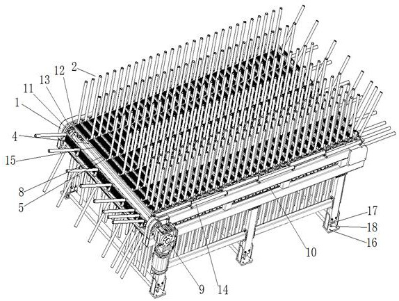
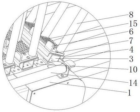
A plate type workpiece transfer equipment
A technology for conveying equipment and workpieces, applied in the field of plate-type workpiece conveying equipment, can solve the problems of increasing the output energy consumption of the power mechanism and the strong work, reducing the working efficiency and service life of the power mechanism, and affecting the safety of equipment use, etc., and achieves exquisite structural design. , The effect of reducing the use of raw materials and improving safety
- Summary
- Abstract
- Description
- Claims
- Application Information
AI Technical Summary
Problems solved by technology
Method used
Image

Examples
Embodiment Construction
[0019] Embodiments of the present invention are described in detail below, examples of which are shown in the drawings, wherein the same or similar reference numerals denote the same or similar elements or elements having the same or similar functions throughout. The embodiments described below by referring to the figures are exemplary only for explaining the present invention and should not be construed as limiting the present invention.
[0020] In describing the present invention, it should be understood that the terms "center", "longitudinal", "transverse", "length", "width", "thickness", "upper", "lower", "front", " Orientation indicated by rear, left, right, vertical, horizontal, top, bottom, inside, outside, clockwise, counterclockwise, etc. The positional relationship is based on the orientation or positional relationship shown in the drawings, which is only for the convenience of describing the present invention and simplifying the description, rather than indicating ...
PUM
 Abstract
Description
Claims
Application Information