Casing gas collection device and method of use

A technology for collecting device and casing gas, which is applied in earth-moving drilling, wellbore/well components, and production fluids, etc., can solve problems such as reduced production capacity, squeezed pump cavity space, constant pressure release valve and shortened system distance, etc. To achieve the effect of reducing flow resistance, increasing liquid production and simple structure

Active Publication Date: 2021-05-25
河北宏龙环保科技有限公司
View PDF0 Cites 0 Cited by
  • Summary
  • Abstract
  • Description
  • Claims
  • Application Information

AI Technical Summary

Problems solved by technology

Part of the casing gas accumulates in the oil casing space, causing the liquid level in the oil well to drop, reducing the effective production pressure difference and production capacity of the oil well; the other part enters the pump chamber with the liquid flow, occupying a certain space in the pump chamber and affecting the pump Efficiency, when it is serious, the "air lock" phenomenon will occur, making the oil well pump unable to work, seriously affecting the normal production and efficiency of the oil well, and if it is discharged outside, it will cause air pollution and waste precious and non-renewable clean resources. vicious circle
At present, most of the mature and applied products are constant pressure release valves, which have the characteristics of low cost and simple structure. When using constant pressure release valves to directly collect them into the production system, the pipeline from the outlet of the constant pressure release valve to the system is particularly easy. The accumulated liquid is easy to condense and cause blockage during production in winter. It is difficult to push the condensed liquid in the pipeline even if the constant pressure release valve is opened.
Although the distance between the constant pressure relief valve and the system is shortened as much as possible in order to overcome this disadvantage, this phenomenon still often occurs
Once the condensate cannot be pushed away, the casing gas cannot be collected normally, so there is an urgent need for a casing gas collection device that overcomes the above-mentioned defects

Method used


Image

  • Casing gas collection device and method of use
  • Casing gas collection device and method of use
  • Casing gas collection device and method of use

Examples


Embodiment Construction

[0031] In order to further understand the content of the present invention, the present invention will be described in detail below in conjunction with specific examples.

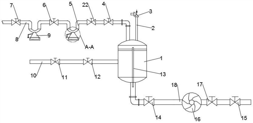
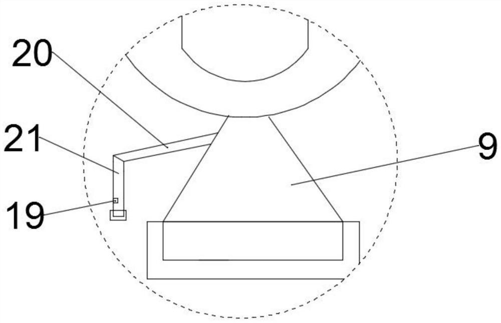
[0032] like Figure 1-4 As shown, according to an embodiment of the casing gas collection device and method of use of the present invention, it includes a casing gas inlet pipeline 8 and a production fluid inlet pipeline 10. The casing gas collection device also includes a buffer tank 1, a gas-liquid Output pipeline 18, the casing gas inlet pipeline 8 is connected to the top of the buffer tank 1 and extends into its interior, the middle part of the side wall of the buffer tank 1 communicates with the production fluid inlet pipeline 10, the The bottom of the buffer tank 1 is connected to the gas-liquid output pipeline 18. An oil-gas mixed delivery pump 16 is arranged on the gas-liquid output pipeline 18. The oil-gas mixed delivery pump 16 transports the gas-liquid to the production system. The inside of the ...


PUM


Abstract

The invention relates to a casing gas collection device, which comprises a casing gas inlet pipeline, a production liquid inlet pipeline, a buffer tank, and a gas-liquid output pipeline. The casing gas inlet pipeline is connected to the top of the buffer tank and extends into Inside, the middle part of the side wall of the buffer tank is connected to the production fluid inlet pipeline; the present invention also includes a method for using a casing gas collection device, which specifically includes the following steps, step S1, detecting casing gas collection The overall airtightness of the device; step S2, turn on the oil-gas mixed delivery pump, and transmit the oil and casing gas to the production system through the oil-gas mixed delivery pump; step S3, detect the liquid level in the storage tank. The invention can ensure the normal opening and closing of the constant-pressure air release valve, avoid blocking the pipeline so that the casing gas cannot be collected, reduce the formation production pressure at the same time, recover the casing gas to the greatest extent, and improve the production efficiency.

Description

technical field [0001] The invention relates to the technical field of oil and gas gathering and transportation, in particular to a casing gas collecting device and a using method. Background technique [0002] During the production process of oil wells in the oil field, a certain amount of oil well natural gas will be volatilized and separated from the annular space between the casing and the oil pipe, also known as casing gas. Part of the casing gas accumulates in the oil casing space, causing the liquid level in the oil well to drop, reducing the effective production pressure difference and production capacity of the oil well; the other part enters the pump chamber with the liquid flow, occupying a certain space in the pump chamber and affecting the pump Efficiency, when it is serious, the "air lock" phenomenon will occur, making the oil well pump unable to work, seriously affecting the normal production and efficiency of the oil well, and if it is discharged outside, it ...

Claims


Application Information

Patent Timeline
Patent Type & Authority Patents(China)
IPC IPC(8): E21B43/00E21B43/12
Inventor 张雪薇周旻李金阳李云峰孟笑天孟兵川
Owner 河北宏龙环保科技有限公司
Why Eureka
Try Eureka