Rotary buckle structure, antenna plate and assembly method thereof

A technology of rotating buckle and assembling method, applied in the direction of antenna support/installation device, etc., can solve the problems of increasing the difficulty of parts classification, increasing the weight and manufacturing cost of the antenna, and reducing the versatility of parts.

Active Publication Date: 2021-08-20
WUHAN HONGXIN TELECOMM TECH CO LTD
View PDF8 Cites 0 Cited by
  • Summary
  • Abstract
  • Description
  • Claims
  • Application Information

AI Technical Summary

Problems solved by technology

[0005] Due to the wide variety of antennas, in order to make the buckle structure suitable for all antenna panels, it is necessary to design the buckle structure according to the thickness of the thickest panel, but this design greatly increases the weight and manufacturing cost of the antenna; Designing different buckle structures increases the types of parts, reduces the versatility of parts, and increases the difficulty of sorting parts

Method used


Image

  • Rotary buckle structure, antenna plate and assembly method thereof
  • Rotary buckle structure, antenna plate and assembly method thereof
  • Rotary buckle structure, antenna plate and assembly method thereof

Examples


Embodiment 1

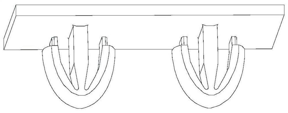
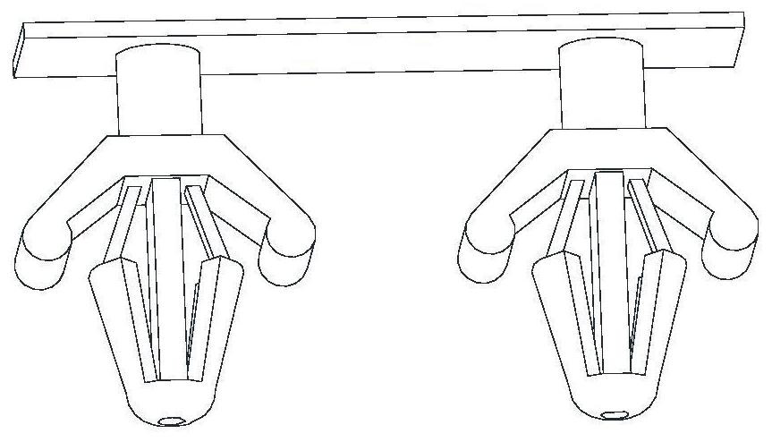
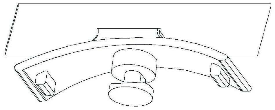
[0031] Figure 4 A preferred embodiment of the rotary buckle structure of the present invention is shown, as Figure 4 and Figure 5 As shown, the rotating buckle structure includes: a top plate 1, a shaft 11, a clamping part 12 and two elastic supporting surfaces 13; the clamping part 12 is arranged on the first end of the shaft 11, and the second end of the shaft 11 Arranged on the top plate; two support surfaces 13 are symmetrically arranged on both sides of the shaft 11 with respect to the axis of the shaft 11, and one end of each support surface 13 is connected to one side of the top plate, and the other end of each support surface is provided with a fixing part ; The fixed part faces the direction where the clamping part 12 is located.

[0032] Specifically, for example, the cross-sectional shape of the shaft 11 may be a circle, an ellipse, a polygon, or the like. And, the clamping part 12 is disposed on the first end of the shaft 11 , for example, the clamping part 1...

Embodiment 2

[0051] Such as Figure 6B As shown, the present invention also provides an antenna panel 2, including: clamping holes 21 and at least one pair of fixing holes provided on the antenna panel 2; the fixing holes are symmetrically arranged around the clamping holes 21; and clamping The hole 21 is opposite to the clamping part 12; there is a certain offset between the fixing hole and the fixing part.

[0052]Specifically, in this embodiment, a pair of fixing holes are provided on the antenna plate 2 as an example for illustration, but this is not intended to limit the protection scope of the present invention. And, a clamping hole 21 is opened on the antenna plate 2 , and the clamping hole 21 is opposite to the clamping part 12 , that is, the clamping hole 21 is used to cooperate with the clamping part 12 . And make the fixing hole position symmetrically arranged around the clamping hole position 21, that is, the arrangement of the fixing hole position and the fixing part is consi...

Embodiment 3

[0057] The present invention also provides a method for assembling the above-mentioned rotating buckle structure and the above-mentioned antenna panel 2, including: placing the clamping part 12 against the clamping hole 21, so that the clamping part 12 is inserted into the clamping hole 21; 11 is rotated at a certain angle, so that the fixing falls into the fixing hole, and the clamping part 12 and the clamping hole 21 are dislocated.

[0058] Specifically, the clamping part 12 of the rotating buckle structure is opposed to the clamping hole 21 of the antenna panel 2, and the clamping part 12 is inserted into the clamping hole 21; after that, the shaft 11 of the rotating buckle structure Rotate at a certain angle, and then drive the supporting surface 13 and the clamping part 12 to rotate at a certain angle, so that the fixing on the supporting surface 13 falls into the fixed hole position, and make the clamping part 12 and the clamping hole 21 misaligned to complete the rotati...


PUM


Abstract

The invention relates to the field of antenna manufacturing, and provides a rotating buckle structure, an antenna panel and an assembly method thereof, wherein the rotating buckle structure includes a top plate, a shaft, a clamping part and two elastic supporting surfaces; the clamping part is arranged on the shaft the first end of the shaft, and the second end of the shaft is arranged on the top plate; two support surfaces are symmetrically arranged on both sides of the shaft with respect to the axis of the shaft, and one end of each support surface is connected to one side of the top plate, and the other end is provided There is a fixed part; the fixed part faces the direction where the clamping part is located. The rotary buckle structure provided by the present invention is provided with a clamping part at one end of the shaft; and a fixed part is provided at the other end of the support surface, so that the rotary buckle structure can be clamped on the antenna plate; The supporting surface is set to be elastic, so that the rotating buckle structure can adapt to antenna plates of different thicknesses, which improves the versatility and reliability of the rotating buckle structure.

Description

technical field [0001] The invention relates to the field of antenna manufacturing, in particular to a rotating buckle structure, an antenna plate and an assembly method thereof. Background technique [0002] At present, most of the structures used to fix or support antennas are made of plastic, and the plastic parts are only suitable for fixing antenna panels with a certain thickness. [0003] figure 1 It shows the plastic parts and buckle structure used to fix the internal components of the antenna; specifically, it is used for fixing the phase shifter and power splitter; figure 2 It shows another plastic part and buckle structure for fixing the internal components of the antenna; specifically, it is used for fixing cables; image 3 It shows the plastic parts and buckle structure used to support the internal components of the antenna; specifically, it is used for the support of the support frame or the transmission parts. [0004] Such as figure 1 As shown, the buckle...

Claims


Application Information

Patent Timeline
Patent Type & Authority Patents(China)
IPC IPC(8): H01Q1/12
Inventor 赖青松程季
Owner WUHAN HONGXIN TELECOMM TECH CO LTD
Why Eureka
Try Eureka