Control structure of power head

A control structure and power head technology, applied in the direction of automatic control devices, manufacturing tools, metal processing machinery parts, etc., can solve the problems of easy-to-crash processing tools, high technical requirements for workers, and low automation, and achieve high automation, Good control effect and reasonable structure design

Inactive Publication Date: 2019-06-04
温岭市雪鹏机械有限公司
View PDF0 Cites 0 Cited by
  • Summary
  • Abstract
  • Description
  • Claims
  • Application Information

AI Technical Summary

Problems solved by technology

Due to the limitation of its structure, CNC feeding cannot be used. When processing the workpiece, it is necessary to manually judge whether the processing tool is in place, and there is a certain error. When the processing is judged to be in place, the spindle head is manually controlled to retreat. Manually control the motor to stop, the degree of automation is low, and the technical requirements for workers are high
Moreover, the power head is fast-feeding during the entire processing process, which is easy to damage the processing tool

Method used


Image

  • Control structure of power head
  • Control structure of power head

Examples


Embodiment Construction

[0015] The following are specific embodiments of the present invention and in conjunction with the accompanying drawings, the technical solutions of the present invention are further described, but the present invention is not limited to these embodiments.

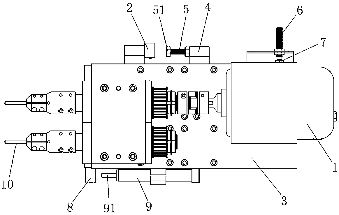
[0016] Such as figure 1 As shown, the control structure of the power head includes a control unit for controlling the motor 1 and cylinder action of the power head, a floor switch 2 arranged on the side of the power head, and a floor switch arranged on the side of the power head supporting plate 3 2. The adjustment switch 4 provided correspondingly, the floor switch 2 and the adjustment switch 4 are respectively connected with the control unit. Such as figure 1 As shown, the adjustment switch 4 is provided with a threaded hole extending along the moving direction of the supporting plate 3, the threaded hole is connected with a bolt 5, and the rod head 51 of the bolt 5 faces the floor switch 2, when the rod head 51 of the ...


PUM


Abstract

The invention provides a control structure of a power head, and belongs to the technical field of machinery. The power head solves the problems that an existing power head is low in automation degreeand poor in control effect. The control structure of the power head comprises a control unit for controlling the action of a motor and an air cylinder of the power head, a ground switch arranged on the side part of the power head, and an adjusting switch which is arranged on the side part of a power head supporting plate and is arranged corresponding to the ground switch, the ground switch and theadjusting switch are correspondingly connected with the control unit, the adjusting switch is provided with a threaded hole extending in the moving direction of the supporting plate, the threaded hole is in inner thread connection with a bolt, the rod head of the bolt faces the ground switch, and when the rod head of the bolt is in contact with the ground switch, the control unit controls a piston rod of the air cylinder to contract. The control structure of the power head has the advantages of being high in automation degree, good in control effect and the like.

Description

technical field [0001] The invention belongs to the technical field of machinery and relates to a control structure, in particular to a control structure of a power head for metal chip processing. Background technique [0002] The faucet handle and the valve core of the faucet are fixedly connected by bolts, and the handle is turned to realize the on-off of the valve core, and the handle is machined with a threaded hole. The traditional processing head for threaded holes includes a supporting plate, a cylinder that drives the supporting plate to move, a spindle head on the supporting plate, and a motor that drives the spindle head. The front end of the spindle head is provided with a processing tool. Process threaded holes on the handle. Due to the limitation of its structure, CNC feeding cannot be used. When processing the workpiece, it is necessary to manually judge whether the processing tool is in place, and there is a certain error. When the processing is judged to be ...

Claims


Application Information

Patent Timeline
Patent Type & Authority Applications(China)
IPC IPC(8): B23Q15/013B23Q5/26
Inventor 陈雪芬
Owner 温岭市雪鹏机械有限公司
Why Eureka
Try Eureka