A hydraulic motor drive mechanism

A driving mechanism and hydraulic motor technology, applied in the field of hydraulic driving equipment, can solve the problems of limited application range of hydraulic motors, short service life of hydraulic motors, serious wear of swash plate, etc., achieve high stability and safety, and prolong service life , Reduce wear effect

Active Publication Date: 2022-02-22
濮阳市凯祥石油设备有限公司
View PDF10 Cites 0 Cited by
  • Summary
  • Abstract
  • Description
  • Claims
  • Application Information

AI Technical Summary

Problems solved by technology

[0005] The invention provides a hydraulic motor driving mechanism, which can provide larger torque at a higher rotational speed, effectively reduce the wear of the internal parts of the hydraulic motor, prolong its service life, and have better stability and safety. High advantage, solves the problem that the rotation angle of the swash plate of the existing plunger hydraulic motor is all located inside it, so that the rotational speed of the drive mechanism is inversely proportional to the torque, if the swash plate angle is larger, The greater the torque will be, but the lower the speed will be. With the continuous development of industrial technology, the working conditions and environment it faces will become more and more complicated, which will greatly limit the scope of application of the hydraulic motor, and Because the hydraulic motor adopts a single-sided tilting drive method, it wears the swash plate seriously during long-term use, resulting in a short service life of the hydraulic motor, and its stability becomes more and more serious with the working conditions. There is a big potential safety hazard in the working environment of high load and high torque

Method used


Image

  • A hydraulic motor drive mechanism
  • A hydraulic motor drive mechanism
  • A hydraulic motor drive mechanism

Examples


Embodiment Construction

[0024] Next, the technical solutions in the embodiments of the present invention will be described in connection with the drawings of the embodiments of the present invention, and it is understood that the described embodiments are merely the embodiments of the present invention, not all of the embodiments. Based on the embodiments of the present invention, all other embodiments obtained by those of ordinary skill in the art are in the range of the present invention without making creative labor premise.

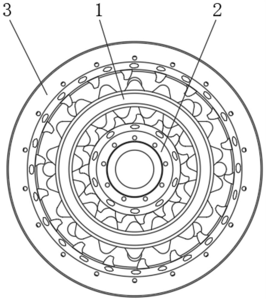
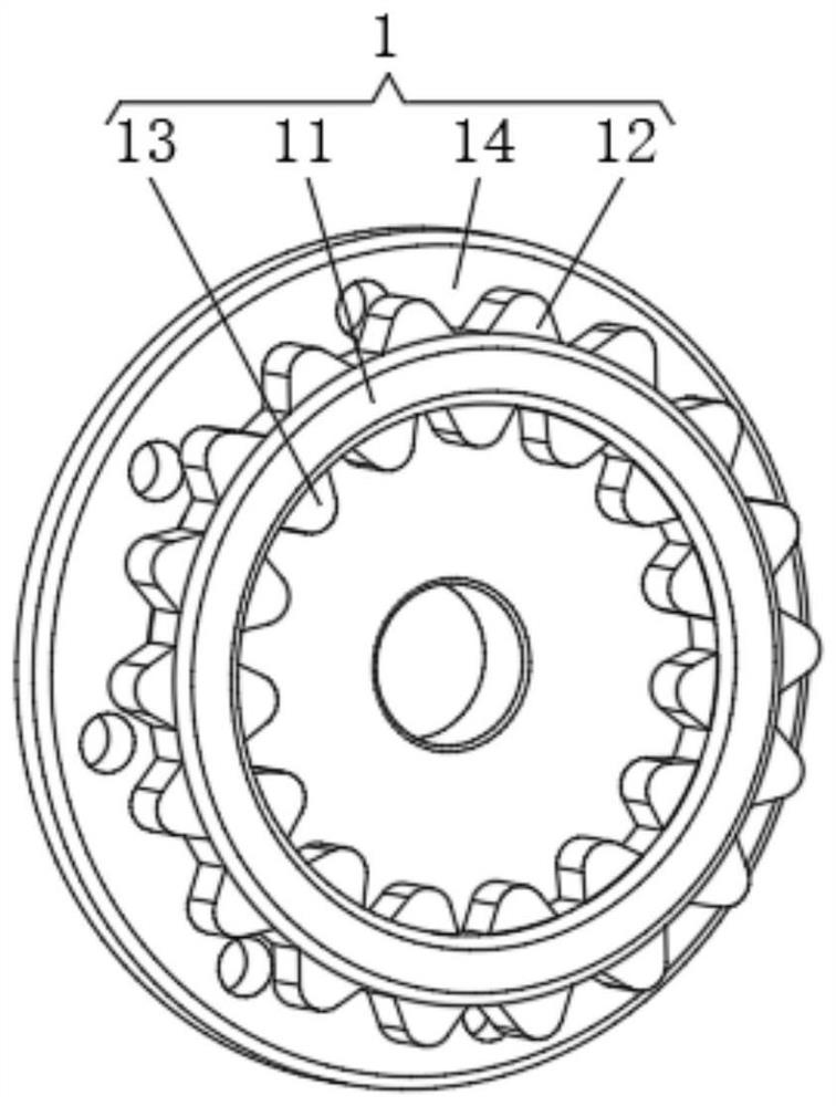
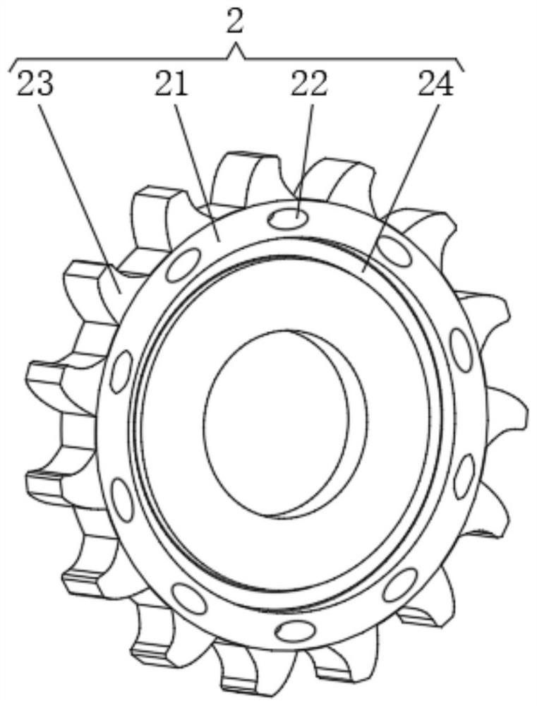
[0025] See Figure 1-5 , A hydraulic motor drive mechanism includes a drive wheel 1, an inner hydraulic mechanism 2, an outer hydraulic mechanism 3, and a hydraulic elastic rubber ring 4, and the internal transmission of the drive wheel 1 is connected to the inner hydraulic mechanism 2, the periphery of the drive wheel 1 The transmission is connected to the outer hydraulic mechanism 3, and the inner cavity of the inner hydraulic mechanism 2 and the outer hydraulic mechanism 3 is ...


PUM


Abstract

The invention relates to the technical field of hydraulic drive equipment, and discloses a hydraulic motor drive mechanism, which includes a transmission runner, an inner hydraulic mechanism, an outer hydraulic mechanism and a hydraulic elastic rubber ring. The periphery of the runner is connected with an external hydraulic mechanism, and a set of hydraulic elastic rubber rings are respectively fixedly installed in the inner chambers of the inner hydraulic mechanism and the outer hydraulic mechanism. The transmission runner includes a transmission ring gear. The hydraulic motor drive mechanism, for the staggered setting between the upper transmission tooth block and the lower transmission tooth block, makes it have better fluency when using the inner hydraulic mechanism and the outer hydraulic mechanism to drive the transmission ring gear to rotate, There will be no pulsation during hydraulic transmission, which further reduces the wear of the hydraulic motor on the swash plate, and at the same time improves the stability of the hydraulic motor under long-term and complicated working conditions.

Description

Technical field [0001] The present invention relates to the technical field of hydraulic driving equipment, and is specifically a hydraulic motor drive mechanism. Background technique [0002] The hydraulic motor acts as a hydraulic system that converts the liquid pressure provided by the hydraulic pump into a hydraulic motor output shaft, that is, the rotational speed and torque converted to a hydraulic motor, which is transmitted as a transfer power and movement. Media, compared to motor drives to provide large torque for mechanical equipment to suit complex working conditions. [0003] Among them, the plunger hydraulic motor is one of the structural forms of the hydraulic motor, which provides a large torque at a higher speed relative to other structural forms, and the entire operation is more stable and does not produce a large pulsation. However, the existing plunger hydraulic motor is located in the inside of its swash plate, so that the speed and torque of the drive mechan...

Claims


Application Information

Patent Timeline
Patent Type & Authority Patents(China)
IPC IPC(8): F03C1/06
CPCF03C1/0607F03C1/0602
Inventor 张代辉
Owner 濮阳市凯祥石油设备有限公司
Why Eureka
Try Eureka